Nissan Juke Service and Repair Manual : Steering switch signal B circuit
Description
Transmits the steering switch signal to audio unit.
Diagnosis Procedure
1.CHECK STEERING SWITCH SIGNAL B CIRCUIT
1. Disconnect audio unit connector and spiral cable connector.
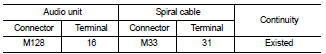
2. Check continuity between audio unit harness connector and spiral cable harness connector.
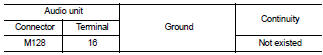
3. Check continuity between audio unit harness connector and ground.
Is the inspection result normal? YES >> GO TO 2.
NO >> Repair harness or connector.
2.CHECK SPIRAL CABLE
Check spiral cable.
Is the inspection result normal? YES >> GO TO 3.
NO >> Replace spiral cable. Refer to SR-16, "Exploded View".
3.CHECK AUDIO UNIT VOLTAGE
1. Connect audio unit connector and spiral cable connector.
2. Turn ignition switch ON.
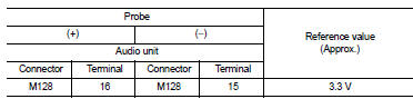
3. Check voltage between audio unit harness connector.
Is the inspection result normal? YES >> GO TO 4.
NO >> Replace audio unit. Refer to AV-38, "Removal and Installation".
4.CHECK STEERING SWITCH
1. Turn ignition switch OFF.
2. Check steering switch. Refer to AV-30, "Component Inspection".
Is the inspection result normal? YES >> INSPECTION END
NO >> Replace steering switch. Refer to AV-44, "Exploded View".
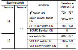
Component Inspection
Measure the resistance between the steering switch connector.
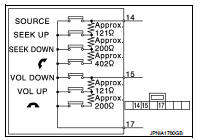
Standard
 Steering switch signal a circuit
Description
Transmits the steering switch signal to audio unit.
Diagnosis Procedure
1.CHECK STEERING SWITCH SIGNAL A CIRCUIT
1. Disconnect audio unit connector and spiral cable connector.
2. Chec ...
 Steering switch ground circuit
Description
Transmits the steering switch signal to audio unit.
Diagnosis Procedure
1.CHECK STEERING SWITCH SIGNAL GROUND CIRCUIT
1. Disconnect audio unit connector and spiral cable connector.
2. ...
Other materials:
Hood lock
Exploded View
1. Hood lock control cable assembly
2. Hood lock assembly
: Clip
: N·m (kg-m, ft-lb)
: Body grease
Hood lock
HOOD LOCK : Removal and Installation
REMOVAL
1. Remove front center grille. Refer to EXT-18, "Removal and Installation".
2. Remove crash zone sensor. Refe ...
Precaution
Service Notice or Precautions for Rear Final Drive
• Check for the correct installation status prior to removal or disassembly.
If matching marks are required, be
certain they do not interfere with the function of the parts when applied.
• Overhaul should be done in a clean work area, it is pre ...
B1135 side air bag module LH
DTC Logic
DTC DETECTION LOGIC
DTC CONFIRMATION PROCEDURE
1.CHECK SELF-DIAG RESULT
With CONSULT-III
1. Turn ignition switch ON.
2. Perform “Self Diagnostic Result” mode of “AIR BAG” using CONSULT-III.
Without CONSULT-III
1. Turn ignition switch ON.
2. Check the air bag warning lamp statu ...
