Nissan Juke Service and Repair Manual : Steering switch signal A circuit
Description
Transmits the steering switch signal to NAVI control unit.
Diagnosis Procedure
1.CHECK STEERING SWITCH SIGNAL A CIRCUIT
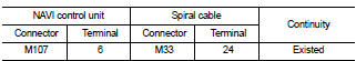
1. Disconnect NAVI control unit connector and spiral cable connector.
2. Check continuity between NAVI control unit harness connector and spiral cable harness connector.
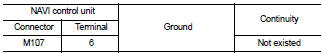
3. Check continuity between NAVI control unit harness connector and ground.
Is the inspection result normal? YES >> GO TO 2.
NO >> Repair harness or connector.
2.CHECK SPIRAL CABLE
Check spiral cable.
Is the inspection result normal? YES >> GO TO 3.
NO >> Replace spiral cable. Refer to SR-16, "Exploded View".
3.CHECK NAVI CONTROL UNIT VOLTAGE
1. Connect NAVI control unit connector and spiral cable connector.
2. Turn ignition switch ON.
3. Check voltage between NAVI control unit harness connector.
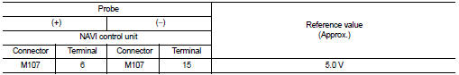
Is the inspection result normal? YES >> GO TO 4.
NO >> Replace NAVI control unit. Refer to AV-84, "Removal and Installation".
4.CHECK STEERING SWITCH
1. Turn ignition switch OFF.
2. Check steering switch. Refer to AV-72, "Component Inspection".
Is the inspection result normal? YES >> INSPECTION END
NO >> Replace steering switch. Refer to AV-91, "Exploded View".
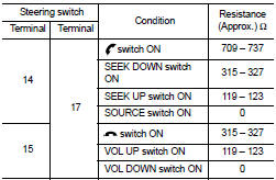
Component Inspection
Measure the resistance between the steering switch connector
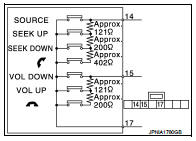
Standard
 Camera image signal circuit
Description
• The NAVI control unit supplies power to the rear view camera when receiving
a reverse signal.
• The rear view camera transmits camera images to the NAVI control unit when
power is ...
 Steering switch signal B circuit
Description
Transmits the steering switch signal to NAVI control unit.
Diagnosis Procedure
1.CHECK STEERING SWITCH SIGNAL B CIRCUIT
1. Disconnect NAVI control unit connector and spiral cable conne ...
Other materials:
Readiness for Inspection/Maintenance (I/M) test
WARNING
A vehicle equipped with All-Wheel Drive (AWD) should never be tested using
a two wheel dynamometer (such as the dynamometers used by some states for emissions
testing), or similar equipment.
Make sure you inform test facility personnel that your vehicle is equipped with
AWD before it ...
B1131 side air bag module RH
DTC Logic
DTC DETECTION LOGIC
DTC CONFIRMATION PROCEDURE
1.CHECK SELF-DIAG RESULT
With CONSULT-III
1. Turn ignition switch ON.
2. Perform “Self Diagnostic Result” mode of “AIR BAG” using CONSULT-III.
Without CONSULT-III
1. Turn ignition switch ON.
2. Check the air bag warning lamp statu ...
Service
• Never use electrical test equipment to check SRS circuits unless instructed
to in this Service Manual.
• Before servicing the SRS, turn ignition switch OFF, disconnect battery
negative terminal and wait 3 minutes
or more. For approximately 3 minutes after the cables are removed, it is still ...
