Nissan Juke Service and Repair Manual : SPEED LIMITER MAIN SWITCH
Component Function Check
1.CHECK SPEED LIMITER MAIN SWITCH FUNCTION
 With CONSULT-III
1. Turn ignition switch ON.
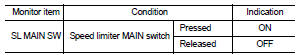
2. Select “SL MAIN SW” in “DATA MONITOR” mode of “ENGINE” using CONSULT-III.
3. Check “SL MAIN SW” indication as per the following condition.
 Without CONSULT-III
1. Turn ignition switch ON.
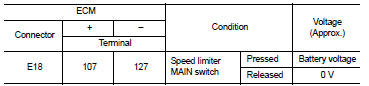
2. Check the voltage between ECM harness connector and ground as per the following conditions.
Is the inspection result normal? YES >> INSPECTION END
NO >> Proceed to EC-432, "Diagnosis Procedure".
Diagnosis Procedure
1.CHECK SPEED LIMITER MAIN SWITCH POWER SUPPLY
1. Turn ignition switch OFF.
2. Disconnect combination switch (spiral cable) harness connector.
3. Turn ignition switch ON.
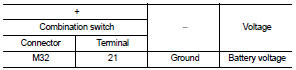
4. Check the voltage between combination switch harness connector and ground.
Is the inspection result normal? YES >> GO TO 2.
NO >> Perform the trouble diagnosis for power supply circuit.
2.CHECK SPEED LIMITER MAIN SWITCH INPUT SIGNAL CIRCUIT
1. Turn ignition switch OFF.
2. Disconnect ECM harness connector.
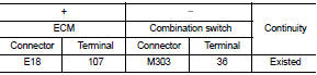
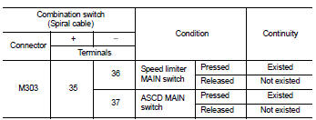
3. Check the continuity between ECM harness connector and combination switch harness connector.
4. Also check harness for short to ground and to power.
Is the inspection result normal? YES >> GO TO 3.
NO >> Repair or replace error-detected parts.
3.CHECK ASCD STEERING SWITCH
Check the ASCD steering switch. Refer to EC-433, "Component Inspection".
Is the inspection result normal? YES >> Check intermittent incident. Refer to GI-42, "Intermittent Incident".
NO >> Replace ASCD steering switch. Refer to ST-9, "Exploded View".
Component Inspection
1.CHECK ASCD STEERING SWITCH-I
1. Disconnect combination switch (spiral cable) harness connector.
2. Check the continuity between combination switch harness connector terminals as per the following conditions.
Is the inspection result normal? YES >> INSPECTION END
NO >> Replace ASCD steering switch. Refer to ST-9, "Exploded View".
2.CHECK ASCD STEERING SWITCH
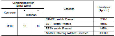
1. Disconnect combination switch (spiral cable) harness connector.
2. Check the resistance between combination switch harness connector terminals as per the following conditions.
Is the inspection result normal? YES >> INSPECTION END
NO >> Replace ASCD steering switch. Refer to ST-9, "Exploded View".
 ASCD main switch
Component Function Check
1.CHECK ASCD MAIN SWITCH FUNCTION
With CONSULT-III
1. Turn ignition switch ON.
2. Select “MAIN SW” in “DATA MONITOR” mode of “ENGINE” using CONSULT-III.
3. Check “MAIN SW ...
 Information display (ASCD)
Component Function Check
1.CHECK INFORMATION DISPLAY
1. Start engine.
2. Press ASCD MAIN switch on ASCD steering switch.
3. Drive the vehicle at more than 40 km/h (25 MPH).
CAUTION:
Always dri ...
Other materials:
Fuel filler lid opener
Exploded View
1. Fuel filler lid opener cable
2. Cable protector
3. Fuel filler lid lock assembly
4. Fuel filler lid assembly
5. Spring
6. Bumper rubber
: Clip
: Do not reuse
Fuel filler lid
FUEL FILLER LID : Removal and Installation
REMOVAL
1. Fully open fuel filler lid.
2. Remov ...
Operating tips (for automatic air conditioner)
• When the engine coolant temperature and outside air temperature are low, the
air flow from the foot outlets may not operate. This is not a malfunction. After
the coolant temperature warms up, air will flow normally from the foot outlets.
• The automatic air conditioner is equipped with se ...
Push-button ignition switch position indicator
Description
Push-button ignition switch changes the power supply position.
BCM maintains the power supply position status.
BCM changes the power supply position with the operation of the push-button
ignition switch.
Component Function Check
1.CHECK FUNCTION
Check push-button ignition swi ...
