Nissan Juke Service and Repair Manual : Speed limiter
SPEED LIMITER : Switch Name and Function
SWITCHES AND INDICATORS
NOTE
:
Shared with ASCD switch.
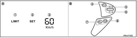
1. Speed limiter indicator
2. SET indicator
3. Set speed indicator
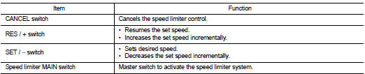
4. CANCEL switch
5. RES / + switch
6. SET / − switch
7. Speed limiter MAIN Switch
8. ASCD MAIN switch
A. On the combination meter
(Information display)
B. On the steering wheel
SET SPEED RANGE
Speed limiter system can be set the following vehicle speed.

SWITCH OPERATION
SET OPERATION
• Press speed limiter MAIN switch. (LIMIT indicated on the information
display)
• By pressing the SET/− switch, the vehicle speed can be set within the range
between 30 km/h and 210 km/h
(in the metric system mode) or 20 MPH and 130 MPH (in the yard/pound system
mode). (SET and set speed
is indicated on the information display)
• When pressing the RES/+ switch, the set speed can be increased.
• When pressing the SET/− switch, the set speed can be decreased.
CANCEL CONDITION
• When any of following conditions exist, speed limiter control is canceled.
- Speed limiter MAIN switch is pressed. (Set speed is cleared.) - ASCD MAIN switch is pressed. (Set speed is cleared.) - CANCEL switch is pressed.
• When accelerator pedal is fully depressed (Kickdown), speed limiter control is temporarily released. And driver can be driven above set speed (Set speed indicator is blinked).
• When the ECM detects any of the following conditions, the ECM cancels the speed limiter operation and informs the driver by blinking speed limiter indicator and SET indicator.
- Malfunction for some self-diagnosis regarding ASCD system.
RESUME OPERATION
After the speed limiter is released by other method than the MAIN switch, the RES/+ switch allows to set the vehicle speed again to the one that is previously set before releasing the speed limiter.
 Operation
AUTOMATIC SPEED CONTROL DEVICE (ASCD)
AUTOMATIC SPEED CONTROL DEVICE (ASCD) : Switch Name and Function
SWITCHES AND INDICATORS
1. CRUISE indicator
2. SET indicator
3. CANCEL switch
4. RES / ...
 On board diagnostic (OBD) system
Diagnosis Description
This system is an on board diagnostic system that records exhaust
emission-related diagnostic information
and detects a sensors/actuator-related malfunction. A malfunction is ...
Other materials:
Inspection
OIL LEAKAGE
Check rear final drive surrounding area (oil seal, drain plug, filler plug,
and carrier case, etc.) for oil leakage.
OIL LEVEL
1. Remove filler plug (1) and check oil level from filler plug mounting
hole as shown in the figure.
CAUTION:
Never start engine while checking oil l ...
Precaution Necessary for Steering Wheel Rotation after Battery Disconnect
NOTE:
• Before removing and installing any control units, first turn the ignition
switch to the LOCK position, then disconnect
both battery cables.
• After finishing work, confirm that all control unit connectors are connected
properly, then re-connect both
battery cables.
• Always use CONS ...
Wiring diagram
SRS AIR BAG SYSTEM
Wiring Diagram
For connector terminal arrangements, harness layouts, and alphabets in a
(option abbreviation; if not
described in wiring diagram), refer to GI-12, "Connector Information/Explanation
of Option Abbreviation".
...
