Nissan Juke Service and Repair Manual : Side air bag (satellite) sensor
Exploded View
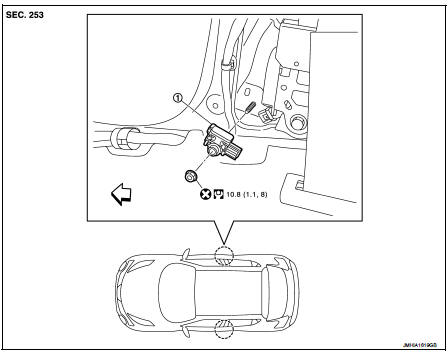
1. Satellite sensor
 : Vehicle front
 : Do not reuse
 : N·m (kg-m, ft-lb)
Removal and Installation
WARNING:
• Before servicing, turn ignition switch OFF, disconnect battery negative
terminal and wait 3 minutes
or more.
• Never use the air tools or electric tools for servicing.
REMOVAL
1. Remove the center pillar lower garnish. Refer to INT-20, "CENTER PILLAR LOWER GARNISH : Removal and Installation".
2. Remove the side air bag (satellite) sensor fixing nut (A), and then pull the side air bag (satellite) sensor (1).
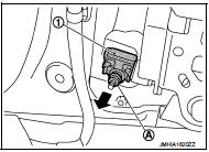
3. Disconnect the harness connector and then remove the side air bag (satellite) sensor.
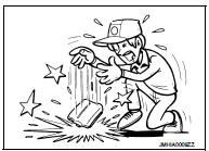
CAUTION:
• Never impact the side air bag (satellite) sensor.
• Replace the side air bag (satellite) sensor if it has been dropped or sustained an impact.
• Replace the side air bag (satellite) sensor of deployed SRS front side air bag module and deployed SRS side curtain air bag module.
INSTALLATION
Note the following items, and then install in the reverse order of removal.
CAUTION:
• Never use the old fixing nut after removal, replace with the new nut.
• Never damage the harness while installing.
• Always install normally aligning to the cutout hole, because performance of the side air bag (satellite) sensor excessively fluctuates according to the installation position.
• If malfunction is detected by the air bag warning lamp, after repair or replacement of the malfunctioning parts, reset the memory using self-diagnosis or CONSULT-III. Refer to SRC-12, "On Board Diagnosis Function" or SRC-16, "CONSULT-III Function".
• After the work is completed, check that no system malfunction is detected by air bag warning lamp
 Crash zone sensor
Exploded View
1. Crash zone sensor
2. Bracket
: Vehicle front
: Do not reuse
N·m (kg-m, ft-lb)
Removal and Installation
WARNING:
• Before servicing, turn ignition switch OFF, disconnect bat ...
 Diagnosis sensor unit
Exploded View
1. Diagnosis sensor unit
: Vehicle front
: Do not reuse
: N·m (kg-m, ft-lb)
Removal and Installation
WARNING:
• Before servicing, turn ignition switch OFF, disconnect battery ne ...
Other materials:
System
METER SYSTEM
METER SYSTEM : System Diagram
*: K9K engine models
METER SYSTEM : System Description
COMBINATION METER
• The combination meter receives necessary signals from each unit, switch,
and sensor to control the following
functions.
- Measuring instruments
- Shift position indicat ...
Headlamp (HI) circuit
Component Function Check
1.CHECK HEADLAMP (HI) OPERATION
CONSULT-III ACTIVE TEST
1. Select “EXTERNAL LAMPS” of IPDM E/R active test item.
2. With operating the test items, check that the headlamp (HI) is turned ON.
Hi : Headlamp (HI) ON
Off : Headlamp (HI) OFF
NOTE:
ON/OFF is repeated 1 seco ...
P0234 TC system
DTC Logic
DTC DETECTION LOGIC
NOTE:
If DTC P0234 is displayed with DTC P0237 or P0238, first perform the trouble
diagnosis for DTC P0237 or
P0238. Refer to EC-260, "DTC Logic".
DTC CONFIRMATION PROCEDURE
1.PERFORM COMPONENT FUNCTION CHECK
Perform component function check. Refer ...
