Nissan Juke Service and Repair Manual : Seat belt buckle switch signal circuit (passenger side)
Diagnosis Procedure
1.CHECK SEAT BELT BUCKLE SWITCH (PASSENGER SIDE) CIRCUIT
1. Turn ignition switch OFF.
2. Disconnect combination meter connector and seat belt buckle switch (passenger side) connector.
3. Check continuity between combination meter harness connector and seat belt buckle switch (passenger side) harness connector.
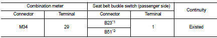
*1: RHD models
*2: LHD models
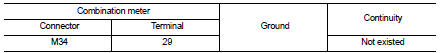
4. Check harness continuity between combination meter harness connector and ground.
Is the inspection result normal? YES >> GO TO 2.
NO >> Repair harness or connector.
2.CHECK SEAT BELT BUCKLE SWITCH (PASSENGER SIDE) GROUND CIRCUIT
Check harness continuity between seat belt buckle switch (passenger side) harness connector and ground.
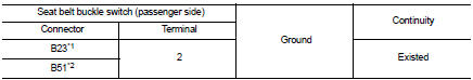
*1: RHD models
*2: LHD models
Is the inspection result normal? YES >> INSPECTION END
NO >> Repair harness or connector.
Component Inspection (Seat Belt Buckle Switch)
1.CHECK SEAT BELT BUCKLE SWITCH (PASSENGER SIDE)
1. Turn ignition switch OFF.
2. Disconnect the seat belt buckle switch (passenger side) connectors.
3. Check continuity between terminals.
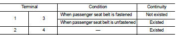
Is the inspection result normal? YES >> INSPECTION END
NO >> Replace the seat belt buckle (passenger side). Refer to SB-8, "SEAT BELT BUCKLE : Removal and Installation".
Component Inspection (Occupant Detection Unit)
1.CHECK OCCUPANT DETECTION UNIT
1. Turn ignition switch OFF.
2. Disconnect the occupant detection unit connector.
3. Check continuity between terminals.
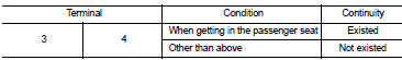
Is the inspection result normal? YES >> INSPECTION END
NO >> Replace the seat cushion trim and pad. Refer to SE-21, "SEAT CUSHION : Disassembly and Assembly" (2WD) or SE-29, "SEAT CUSHION : Disassembly and Assembly" (4WD).
 Seat belt buckle switch signal circuit (driver side)
Component Function Check
1.CHECK COMBINATION METER INPUT SIGNAL
Select the “Data Monitor” for the “METER/M&A” and check the “BUCKLE SW”
monitor value.
BUCKLE SW
When driver seat belt is fast ...
 A/C auto AMP. Connection recognition signal circuit
Diagnosis Procedure
1.CHECK A/C AUTO AMP. CONNECTION RECOGNITION SIGNAL
1. Turn ignition switch ON.
2. Check voltage between combination meter harness connector and ground.
Is the inspection res ...
Other materials:
B1086 seat belt Pre-tensioner LH
DTC Logic
DTC DETECTION LOGIC
DTC CONFIRMATION PROCEDURE
1.CHECK SELF-DIAG RESULT
With CONSULT-III
1. Turn ignition switch ON.
2. Perform “Self Diagnostic Result” mode of “AIR BAG” using CONSULT-III.
Without CONSULT-III
1. Turn ignition switch ON.
2. Check the air bag warning lamp statu ...
Power supply and ground circuit
Diagnosis Procedure
1.CHECK ABS ACTUATOR AND ELECTRIC UNIT (CONTROL UNIT) IGNITION POWER
SUPPLY
1. Turn the ignition switch OFF.
2. Disconnect ABS actuator and electric unit (control unit) harness connector.
3. Check voltage between ABS actuator and electric unit (control unit) harness
conne ...
P0130 A/F sensor 1
DTC Logic
DTC DETECTION LOGIC
To judge the malfunction, the diagnosis checks that the A/F signal computed
by ECM from the A/F sensor 1
signal fluctuates according to fuel feedback control.
DTC CONFIRMATION PROCEDURE
1.PRECONDITIONING
If DTC Confirmation Procedure has been previously conduc ...
