Nissan Juke Service and Repair Manual : Sample/Wiring Diagram -Example-
Each section includes wiring diagrams.
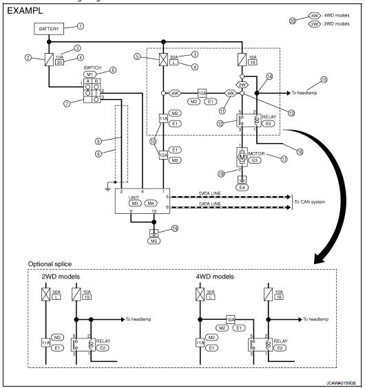
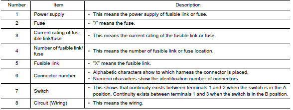
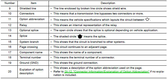
Description
SWITCH POSITIONS
Switches are shown in wiring diagrams as if the vehicle is in the “normal” condition.
A vehicle is in the “normal” condition when: • ignition switch is “OFF”, • doors, hood and trunk lid/back door are closed, • pedals are not depressed, and • parking brake is released.
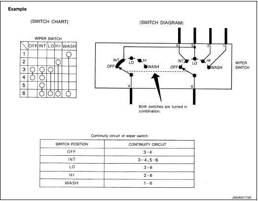
MULTIPLE SWITCH
The continuity of multiple switch is described in two ways as shown below.
• The switch chart is used in schematic diagrams.
• The switch diagram is used in wiring diagrams.
 Connector Symbols
Most of connector symbols in wiring diagrams are shown from the terminal
side.
• Connector symbols shown from the terminal side are enclosed by
a single line and followed by the direction mark.
...
 Connector Information/Explanation of Option Abbreviation
CONNECTOR LIST
Connector information and harness layout are described in “POWER SUPPLY,
GROUND & CIRCUIT ELEMENTS”
Section.
EXPLANATION OF OPTION ABBREVIATION
HOW TO USE CONNECTOR INFORM ...
Other materials:
Front fender
Exploded View
1. Front fender assembly
2. Front fender stiffener
: Vehicle front
Removal and Installation
REMOVAL
1. Remove front fillet molding. Refer to EXT-26, "FRONT FILLET MOLDING :
Removal and Installation".
2. Remove front bumper fascia assembly. Refer to EXT-13, "R ...
Audible reminders
Key reminder chime
Models with Intelligent Key system:
A chime will sound if the driver side door is opened while the ignition switch
is pushed to the ACC position.
Make sure the ignition switch is pushed to the OFF position, and take the Intelligent
Key with you when leaving the vehicle.
Mo ...
Removal and Installation
REMOVAL
1. Separate the rear propeller shaft. Refer to DLN-121, "Removal and
Installation".
2. Remove right side drive shaft. Refer to FAX-24, "RIGHT SIDE : Removal and
Installation".
3. Remove catalyst convertor support bracket (RH). EM-35, "4WD : Removal and
Insta ...
