Nissan Juke Service and Repair Manual : S terminal circuit
Description
The starter motor magnetic switch is supplied with power when the ignition switch is turned to the START position while the selector lever is in the P or N position for CVT models or the clutch pedal is depressed for M/T models.
Diagnosis Procedure
CAUTION:
Perform diagnosis under the condition that engine cannot start by the following
procedure.
1. Remove fuel pump fuse.
2. Crank or start the engine (where possible) until the fuel pressure is released.
1.CHECK “S” TERMINAL CIRCUIT
1. Turn ignition switch OFF.
2. Disconnect starter motor connector.
3. Shift selector lever to “P” or “N” position. (CVT models) Keep depressing clutch pedal fully. (M/T models) 4. Check voltage between starter motor harness connector and ground.
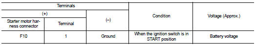
Is the inspection result normal? YES >> “S” terminal circuit is OK. Further inspection is necessary. Refer to STR-14, "Work Flow".
NO >> GO TO 2.
2.CHECK HARNESS CONTINUITY (OPEN CIRCUIT)
1. Disconnect IPDM E/R connector.
2. Check continuity between starter motor harness connector and IPDM E/R harness connector.
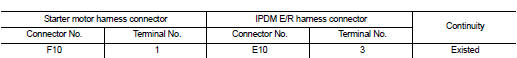
Is the inspection result normal? YES >> Further inspection is necessary. Refer to STR-14, "Work Flow".
NO >> Repair the harness.
 B terminal circuit
Description
The “B” terminal is constantly supplied with battery power.
Diagnosis Procedure
CAUTION:
Perform diagnosis under the condition that engine cannot start by the following
procedure.
...
 Symptom diagnosis
STARTING SYSTEM
Symptom Table
...
Other materials:
Front passenger air bag module
Exploded View
1. Front passenger air bag module
2. Instrument panel assembly
: Pawl
: Do not reuse
: N·m (kg-m, ft-lb)
Removal and Installation
WARNING:
• Before servicing, turn ignition switch OFF, disconnect battery negative
terminal and wait 3 minutes
or more.
• Always work from th ...
Operating range for engine start function
The Intelligent Key can only be used for starting the engine when the Intelligent
Key is within the specified operating range1 .
When the Intelligent Key battery is almost discharged or strong radio waves are
present near the operating location, the Intelligent Key system’s operating range
...
Speed limiter
Speed limiter : System Diagram
Speed limiter : System Description
INPUT/OUTPUT SIGNAL CHART
*: This signal is sent to the ECM through CAN communication line
BASIC SPEED LIMITER SYSTEM
• Speed limiter is a system that enables to restrict the vehicle speed within
the set speed that is sele ...
