Nissan Juke Service and Repair Manual : Removal and installation
MULTI DISPLAY UNIT
Exploded View
REMOVAL
Refer to IP-12, "Exploded View".
DISASSEMBLY
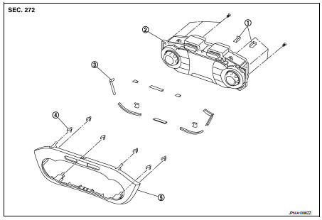
1. Silencer tape
2. Multi display unit
3. Silencer tape
4. Clip
5. Control finisher
Removal and Installation
REMOVAL
Refer to IP-12, "Exploded View".
CAUTION:
• When performing the work, use a shop cloth to protect the parts from damage.
• Always fix the harness clamp in position.
INSTALLATION
Install in the reverse order of removal.
 Basic inspection
DIAGNOSIS AND REPAIR WORK FLOW
Work Flow
DESCRIPTION OF TROUBLE DIAGNOSIS FLOWCHART
DETAILS OF TROUBLE DIAGNOSIS FLOWCHART
1.OBTAIN INFORMATION ABOUT SYMPTOM
Interview the customer to obtain as ...
 Maintenance
...
Other materials:
P0132 A/F sensor 1
DTC Logic
DTC DETECTION LOGIC
To judge the malfunction, the diagnosis checks that the A/F signal computed
by ECM from the A/F sensor 1
signal is not inordinately high.
DTC CONFIRMATION PROCEDURE
1.PRECONDITIONING
If DTC Confirmation Procedure has been previously conducted, always perform
...
Audio unit
Removal and Installation
REMOVAL
1. Remove cluster lid C. Refer to IP-12, "Exploded View".
2. Remove audio unit screws.
3. Disconnect audio unit connectors to remove audio unit and brackets as a
single unit.
4. Remove brackets screws to remove audio unit.
INSTALLATION
1. Install ...
Power supply routing circuit
Wiring Diagram - Battery power supply -
For connector terminal arrangements, harness layouts, and alphabets in a
(option abbreviation; if not
described in wiring diagram), refer to GI-12, "Connector Information/Explanation
of Option Abbreviation".
Wiring Diagram - Accessory p ...
