Nissan Juke Service and Repair Manual : Removal and Installation
REMOVAL
1. Remove rear propeller shaft assembly. Refer to DLN-121, "Removal and Installation".
2. Remove rear drive shaft. Refer to RAX-17, "Removal and Installation".
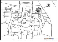
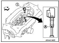
3. Disconnect sub-harness connector (1).
4. Remove rear final drive breather hose.
5. Support rear final drive assembly with a suitable jack.
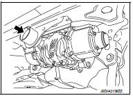
6. Remove rear final drive mounting bolt (
) at rear suspension
member.
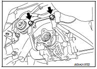
7. Remove final drive mounting bolts and nuts (
), and then
remove rear final drive assembly from final drive mounting
bracket.
CAUTION:
Secure final drive assembly to a suitable jack while removing
it.
8. Remove fuel tank. Refer to FL-23, "4WD : Removal and Installation".
9. Remove final drive mounting bracket.
INSTALLATION
Note the following, and install in the reverse order of removal.
• Install the breather hose (1) to breather tube until dimension (A) shown as follows.
A:
Final drive side : 20mm (0.79 in)
Breather side : 20mm (0.79 in)
CAUTION:
• Never reuse hose clamps.
• Install the hose clamps, with the tab facing vehicle rear.
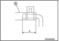
• If remove breather hose, install breather hose (1) as shown in the figure.
Vehicle front
- Install breather hose with paint mark (A) facing vehicle rear.
• When oil leaks while removing final drive assembly, check oil level after the installation. Refer to DLN-132, "Inspection".
• When replacing rear final drive assembly, perform writing unit parameter. Refer to DLN-39, "Work Procedure".
 Exploded View
1. Final drive mounting bracket
2. Washer
3. Rear final drive assembly
: Vehicle front
: N·m (kg-m, ft-lb)
: Never reuse parts
: Apply multi purpose grease
: Apply gear oil.
...

Other materials:
U1000 can comm circuit
Description
CAN (Controller Area Network) is a serial communication line for real time
application. It is an on-vehicle multiplex
communication line with high data communication speed and excellent error
detection ability. Many electronic
control units are equipped onto a vehicle, and each co ...
Fender protector
Exploded View
1. Hoodledge insurator
2. Fender protector
3. U nut
4. Air guide
5. Screw grommet
A. To hoodledge panel
: Vehicle front
Removal and Installation
REMOVAL
1. Remove front fillet molding. Refer to EXT-26, "FRONT FILLET MOLDING :
Removal and Installation".
2. Re ...
DTC Index
*1: 1st trip DTC No. is the same as DTC No.
*2: This number is prescribed by SAE J1979/ ISO 15031-5.
*3: In Diagnostic Test Mode II (Self-diagnostic results), this number is
controlled by NISSAN.
*4: The troubleshooting for this DTC needs CONSULT-III.
*5: When the fail-safe operation ...
