Nissan Juke Service and Repair Manual : Removal and Installation
REMOVAL
• Disconnect each joint and mounting.
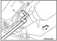
• Remove heated oxygen sensor 2 with following procedure:
- Using heated oxygen sensor wrench [SST: KV10114400] (A), removal heated oxygen sensor 2 (1).
CAUTION:
Be careful not to damage heated oxygen sensor 2.
INSTALLATION
Note the following, and install in the reverse order of removal.
CAUTION:
• Always replace seal bearings with new ones when reassembling.
• Discard any heated oxygen sensor 2 which has been dropped onto a hard surface such as a concrete floor. Use a new one.
• Before installing a new heated oxygen sensor 2, clean exhaust system threads using the heated oxygen sensor thread cleaner [commercial service tool: J-43897-18 or J-43897-12] and apply anti-seize lubricant (commercial service tool).
• Never over torque heated oxygen sensor 2. Doing so may cause damage to the heated oxygen sensor 2, resulting in the “MIL” coming on.
• If heat insulator is badly deformed, repair or replace it. If deposits such as mud pile up on the heat insulator, remove them.
• When installing heat insulator avoid large gaps or interference between heat insulator and each exhaust pipe.
• Remove deposits from the sealing surface of each connection. Connect them securely to avoid gas leakage.
• When installing each mounting rubber, use silicon oil to avoid twisting.
• Temporarily tighten mounting nuts and bolts. Check each part for unusual interference and mounting rubber interference, and then tighten them to the specified torque.
• When installing each mounting rubber, avoid twisting or unusual extension in up/down, front/rear and right/left directions.
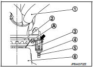
Exhaust Manifold to Exhaust Front Tube 1. Securely insert seal bearing (2) into exhaust manifold (1) side in the direction shown in the figure.
3 : Spring
4 : Nut
5 : Stud bolt
6 : Exhaust front tube
CAUTION:
Be careful not to damage seal bearing surface when installing.
2. With spring, tighten nut.
CAUTION:
• Fasten stud bolts to the flange of exhaust manifold side to the specified
torque before fastening
mounting nuts.
• Ensure springs are seated correctly on the flange and not sitting on (A).
• Be careful that stud bolt does not interfere with mounting hole of exhaust
front tube ( ).
).
3. After installing, check that stud bolt does not interfere with mounting hole of exhaust front tube.
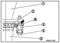
Exhaust Front Tube to Center Muffler
1. Securely insert seal bearing (2) into exhaust front tube (1) side in the direction shown in the figure.
3 : Spring
4 : Bolt
5 : Center muffler
CAUTION:
Be careful not to damage seal bearing surface when installing.
2. With spring, tighten bolt.
CAUTION:
• Ensure springs are seated correctly on the flange and not sitting on (A).
• Be careful that bolt does not interfere with mounting hole of center muffler (
 ).
).
3. After installing, check that bolt does not interfere with mounting hole of center muffler.
 Exploded View
1. Mounting rubber
2. Main muffler
3. Seal bearing
4. Spring
5. Mounting rubber
6. Seal bearing
7. Exhaust front tube
8. Heated oxygen sensor 2
9. Sub muffler
10. Gasket
: Always rep ...
 Inspection
INSPECTION AFTER INSTALLATION
• Check clearance between tail tube and rear bumper is even.
• With engine running, check exhaust tube joints for gas leakage and unusual
noises.
• Check to ensure t ...
Other materials:
Maintenance precautions
When performing any inspection or maintenance work on your vehicle, always take
care to prevent serious accidental injury to yourself or damage to the vehicle.
The following are general precautions which should be closely observed.
WARNING
• Park the vehicle on a level surface, apply the ...
C1109 power and ground system
DTC Logic
DTC DETECTION LOGIC
DTC CONFIRMATION PROCEDURE
1.PRECONDITIONING
If “DTC CONFIRMATION PROCEDURE” has been previously conducted, always turn
ignition switch OFF and
wait at least 10 seconds before conducting the next test.
>> GO TO 2.
2.CHECK DTC DETECTION
With CONSULT ...
Manual Transmission (MT)
WARNING
• Do not downshift abruptly on slippery roads. This may cause a loss
of control.
• Do not over-rev the engine when shifting to a lower gear. This may cause a loss
of control or engine damage.
• When the high fluid temperature protection mode or fail-safe operation occurs,
vehi ...
