Nissan Juke Service and Repair Manual : Remote keyless entry receiver
Component Function Check
1.CHECK FUNCTION
1. Select “INTELLIGENT KEY” of “BCM” using CONSULT-III.
2. Select “RKE OPE COUN1” in “DATA MONITOR” mode.
3. Check that the function operates normally according to the following conditions.

Is the inspection result normal? YES >> Remote keyless entry receiver is OK.
NO >> Refer to DLK-95, "Diagnosis Procedure".
Diagnosis Procedure
1.CHECK REMOTE KEYLESS ENTRY RECEIVER GROUND CIRCUIT
1. Turn ignition switch OFF.
2. Disconnect BCM connector and remote keyless entry receiver connector.
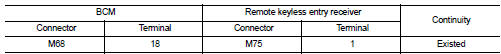
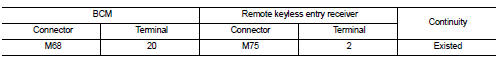
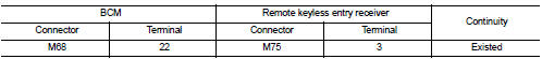
3. Check continuity between BCM harness connector and remote keyless entry receiver harness connector.
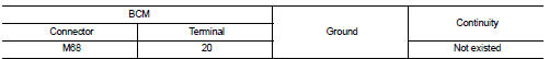
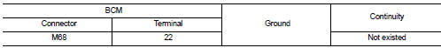
4. Check continuity between BCM harness connector and ground.

Is the inspection result normal? YES >> GO TO 2.
NO >> Repair or replace harness.
2.CHECK REMOTE KEYLESS ENTRY RECEIVER POWER SUPPLY
1. Reconnect BCM connector.
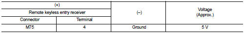
2. Check voltage between remote keyless entry receiver harness connector and ground.
Is the inspection result normal? YES >> GO TO 4.
NO >> GO TO 3.
3.CHECK REMOTE KEYLESS ENTRY RECEIVER CIRCUIT 1
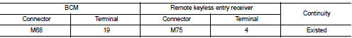
1. Disconnect BCM connector 2. Check continuity between BCM harness connector and remote keyless entry receiver harness connector.
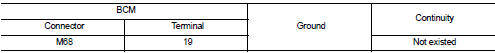
3. Check continuity between BCM harness connector and ground.
Is the inspection result normal? YES >> Replace BCM. Refer to BCS-93, "Removal and Installation".
NO >> Repair or replace harness.
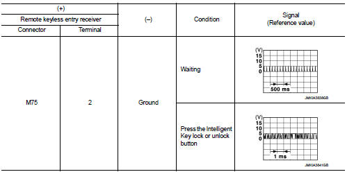
4.CHECK REMOTE KEYLESS ENTRY RECEIVER OUTPUT SIGNAL
1. Reconnect remote keyless entry receiver connector.
2. Check signal between remote keyless entry receiver harness connector and ground using oscilloscope.
Is the inspection result normal? YES >> GO TO 5.
NO >> Replace remote keyless entry receiver.
5.CHECK REMOTE KEYLESS ENTRY RECEIVER CIRCUIT 2
1. Disconnect BCM connector and remote keyless entry receiver connector.
2. Check continuity between BCM harness connector and remote keyless entry receiver harness connector.
3. Check continuity between BCM harness connector and ground.
Is the inspection result normal? YES >> GO TO 6.
NO >> Repair or replace harness.
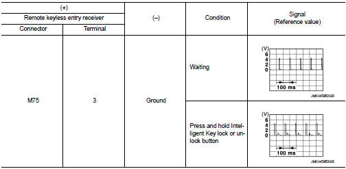
6.CHECK REMOTE KEYLESS ENTRY RECEIVER RSSI OUTPUT SIGNAL
1. Reconnect BCM and remote keyless entry receiver connector.
2. Check signal between remote keyless entry receiver harness connector and ground using oscilloscope.
Is the inspection result normal? YES >> GO TO 7.
NO >> Replace remote keyless entry receiver.
7.CHECK REMOTE KEYLESS ENTRY RECEIVER RSSI CIRCUIT
1. Disconnect BCM and remote keyless entry receiver connector.
2. Check continuity between BCM harness connector and remote keyless entry receiver harness connector.
3. Check continuity between BCM harness connector and ground.
Is the inspection result normal? YES >> Replace BCM. Refer to BCS-93, "Removal and Installation".
NO >> Repair or replace harness.
 Key warning lamp
Component Function Check
1.CHECK FUNCTION
1. Select “INTELLIGENT KEY” of “BCM” using CONSULT-III.
2. Select “INDICATOR” in “ACTIVE TEST” mode.
3. Check that the function operates normally accordin ...
 Shift P warning lamp
Component Function Check
1.CHECK FUNCTION
1. Select “INTELLIGENT KEY” of “BCM” using CONSULT-III.
2. Select “LCD” in “ACTIVE TEST” mode.
3. Check that the function operates normally according to t ...
Other materials:
P2119 electric throttle control actuator
DTC Logic
DTC CONFIRMATION PROCEDURE
1.PRECONDITIONING
If DTC Confirmation Procedure has been previously conducted, always perform
the following procedure
before conducting the next test.
1. Turn ignition switch OFF and wait at least 10 seconds.
2. Turn ignition switch ON.
3. Turn ignitio ...
Power supply routing circuit
Wiring Diagram - Battery power supply -
For connector terminal arrangements, harness layouts, and alphabets in a
(option abbreviation; if not
described in wiring diagram), refer to GI-12, "Connector Information/Explanation
of Option Abbreviation".
Wiring Diagram - Accessory p ...
Replacing
Replace the wiper blades if they are worn.
Before replacing the wiper blades, the wiper should be in the fully up position
to avoid scratching the engine hood or damaging the wiper arm. To pull up the wiper
arm, see “Windshield wiper and washer switch” .
1. Lift the wiper arm away from the w ...
