Nissan Juke Service and Repair Manual : Rear window defogger relay
Description
The rear window defogger is operated by turning the rear window defogger switch ON.
Component Function Check
1.CHECK FUNCTION
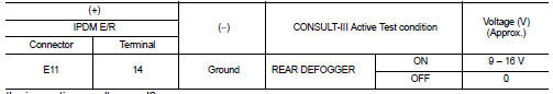
1. Perform IPDM E/R Active Test (“REAR DEFOGGER”) using CONSULT-III.
2. Touch “ON”.
3. Check that the rear window heating wire is getting warmer.
Is the inspection result normal? YES >> Rear window defogger relay function is OK.
NO >> Refer to DEF-30, "Diagnosis Procedure"
Diagnosis Procedure
1.CHECK FUSE
1. Turn ignition switch OFF.
2. Check the 20A fuse (No. 41 located in IPDM E/R).
Is the inspection result normal? YES >> GO TO 2.
NO >> Replace the blown fuse after repairing the affected circuit if a fuse is blown.
2.CHECK IPDM E/R OUTPUT SIGNAL
1. Perform IPDM E/R Active Test (“REAR DEFOGGER”) using CONSULT-III.
2. Touch “ON”.
3. Check voltage between IPDM E/R harness connector and ground.
Is the inspection result normal? YES >> INSPECTION END
NO >> Replace IPDM E/R. Refer to PCS-34, "Removal and Installation" (With Intelligent Key system) or PCS-63, "Removal and Installation" (Without Intelligent Key system).
 Rear window defogger switch
With auto A/C
WITH AUTO A/C : Description
• The rear window defogger is operated by turning the rear window defogger
switch ON.
• The indicator lamp in the rear window defogger switch illuminates ...
 Rear window defogger
Description
Heats the heating wire with the power supply from the rear window defogger
relay to prevent the rear window
from fogging up.
Component Function Check
1.CHECK FUNCTION
1. Perform IPD ...
Other materials:
Removal and Installation Procedure for CVT Unit Connector
REMOVAL
Rotate bayonet ring (1) counterclockwise, pull out CVT unit harness
connector (2) upward and remove it.
INSTALLATION
1. Align Δ marking on CVT unit harness connector terminal body
with marking on bayonet ring, insert CVT unit harness connector,
and then rotate bayonet ...
Combination switch
Exploded View
1. Combination switch
2. Combination switch connector
Removal and Installation
REMOVAL
1. Remove steering column cover. Refer to IP-13, "Removal and
Installation".
2. Remove screws.
3. Disconnect the connector.
4. Pull up the combination switch to remove it.
I ...
Charge air cooler
Exploded View
1. Air inlet hose
2. Clamp
3. Air inlet tube
4. Air inlet hose
5. Charge air cooler
6. Air inlet hose
7. Air inlet tube
8. Turbocharger
9. Air inlet tube assembly
A. 1st step: 5.0 N·m (0.51 kg-m, 44 ft-lb)
2nd step: 7.0 N·m (0.71 kg-m, 62 ftlb)
B. Paint mark
C. T ...
