Nissan Juke Service and Repair Manual : Rear wheel hub and housing
Exploded View
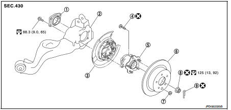
1. Axle housing
2. Suspension arm
3. Back plate
4. Hub bolt
5. Wheel hub assembly (Bearing-integrated
type)
6. Disc rotor
7. Plug
8. Wheel hub lock nut
9. Cotter pin
 : Always replace after every
disassembly.
 : N·m (kg-m, ft-lb)
Removal and Ins
REMOVAL
1. Remove tires. Refer to WT-7, "Removal and Installation".
2. Remove wheel sensor. Refer to BRC-86, "REAR WHEEL SENSOR : Removal and Installation" (without ESP), BRC-227, "REAR WHEEL SENSOR : Removal and Installation" (with ESP).
3. Remove caliper assembly. Hang caliper assembly in a place where it will not interfere with work. Refer to BR-65, "BRAKE CALIPER ASSEMBLY : Removal and Installation" (LHD), BR-131, "BRAKE CALIPER ASSEMBLY : Removal and Installation" (RHD).
CAUTION:
Never depress brake pedal while brake caliper is remove
d.
4. Remove disc rotor. If disc rotor cannot be removed, remove as follows.
CAUTION:
• Parking brake completely in the released position.
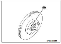
• Put matching marks (A) on the wheel hub assembly and the disc rotor before removing the disc rotor.
• Never drop disc rotor.
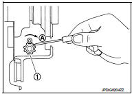
a. Fix the disc rotor with wheel nuts and remove the adjusting hole plug.
b. Using suitable tool, rotate adjuster (1) in the direction (A) to retract and loosen brake shoe.
5. Remove cotter pin, and then loosen wheel hub lock nut.
6. Patch wheel hub lock nut with a piece of wood. Hammer the wood to disengage wheel hub assembly from drive shaft.
CAUTION:
• Never place drive shaft joint at an extreme angle. Also be
careful not to overextend slide joint.
• Never allow drive shaft to hang down without support for joint sub-assembly, shaft and the other parts.
NOTE:
Use suitable puller, if wheel hub assembly and drive shaft cannot be separated even after performing the above procedure.
7. Remove wheel hub lock nut.
8. Remove wheel hub assembly.
CAUTION:
Never remove rear brake assembly. Protect it from falling.
9. If axle housing need to be removed, remove drive shaft. Refer to RAX-17, "Removal and Installation".
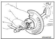
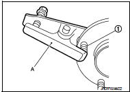
10. Remove hub bolts (1) from wheel hub assembly, using the ball joint remover (A) (commercial service tool).
CAUTION:
• Remove hub bolt only when necessary.
• Never hammer the hub bolt to avoid impact to the wheel hub assembly.
• Pull out the hub bolt in a direction perpendicular to the wheel hub assembly.
11. Perform inspection after removal. Refer to RAX-15, "Inspection".
INSTALLATION Note the following, and install in the reverse order of the removal.
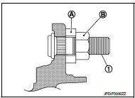
• Place a washer (A) as shown in the figure to install the hub bolts (1) by using the tightening force of the nut (B).
CAUTION:
• Check that there is no clearance between wheel hub assembly
and hub bolt.
• Never reuse hub bolt.
• Never reuse wheel hub lock nut and cotter pin.
• Align the matching marks that have been made during removal when reusing the disc rotor.
• Perform inspection after installation. Refer to RAX-15, "Inspection".
Inspection
INSPECTION AFTER REMOVAL
Check wheel hub assembly for wear, cracks, and damage. Replace if necessary.
INSPECTION AFTER INSTALLATION
1. Check wheel sensor harness for proper connection. BRC-85, "REAR WHEEL SENSOR : Exploded View" (Without ESP), BRC-225, "REAR WHEEL SENSOR : Exploded View" (With ESP).
2. Adjust parking brake operation (stroke). Refer to PB-2, "Inspection and Adjustment".
3. Check wheel alignment. Refer to RSU-20, "Inspection".

 Rear drive shaft
Exploded View
1. Circular clip
2. Dust shield
3. Housing
4. Snap ring
5. Ball cage/steel ball/inner race assembly
6. Stopper ring
7. Boot band
8. Boot
9. Shaft
10. Joint sub-assembly ...
Other materials:
P012B TC boost sensor
DTC Logic
DTC DETECTION LOGIC
Diagnosis Procedure
1.CHECK GROUND CONNECTIONS
1. Turn ignition switch OFF.
2. Check ground connection E38. Refer to Ground inspection in GI-44, "Circuit
Inspection".
Is the inspection result normal?
YES >> GO TO 2.
NO >> Repair or ...
B1068, B1073 passenger air bag module
DTC Logic
DTC DETECTION LOGIC
DTC CONFIRMATION PROCEDURE
1.CHECK SELF-DIAG RESULT
With CONSULT-III
1. Turn ignition switch ON.
2. Perform “Self Diagnostic Result” mode of “AIR BAG” using CONSULT-III.
Without CONSULT-III
1. Turn ignition switch ON.
2. Check the air bag warning lamp statu ...
EGR volume control valve closed position learning
Description
EGR Volume Control Valve Closed Position Learning is an operation to learn
the fully closed position of the
EGR volume control valve by monitoring the EGR volume control valve control
position sensor output signal.
Work Procedure
1.START
1. Turn ignition switch ON.
2. Perform ? ...
