Nissan Juke Service and Repair Manual : Rear suspension assembly
Exploded View
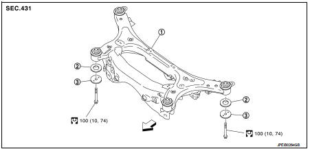
1. Rear suspension member
2. Rebound stopper
3. Washer
 : Vehicle front
 N·m (kg-m, ft-lb)
Removal and Installation
REMOVAL
1. Remove tires. Refer to WT-7, "Removal and Installation".
2. Remove center pipe. Refer to EX-6, "Removal and Installation".
3. Remove propeller shaft. Refer to DLN-121, "Removal and Installation".
4. Remove stabilizer bar. Refer to RSU-34, "Removal and Installation".
5. Remove wheel sensor and sensor harness. Refer to BRC-86, "REAR WHEEL SENSOR : Removal and Installation" (Without ESP), BRC-227, "REAR WHEEL SENSOR : Removal and Installation" (With ESP).
6. Remove upper link from suspension arm. Refer to RSU-32, "Removal and Installation".
7. Remove lower link from suspension arm. Refer to RSU-30, "Removal and Installation".
8. Remove drive shaft from rear final drive. Refer to RAX-17, "Removal and Installation".
9. Remove rear final drive. Refer to DLN-144, "Removal and Installation".
10. Set jack under rear suspension member.
CAUTION:
• Never damage the suspension member with a jack.
• Check the stable condition when using a jack.
11. Remove rear suspension member mounting bolts, rebound stopper, and washer.
12. Slowly lower jack, then remove rear suspension member, lower link and upper link from vehicle as a unit.
CAUTION:
Operate while checking that jack supporting status is stable.
13. Remove lower link and upper link from rear suspension member.
14. Perform inspection after removal. Refer to RSU-36, "Inspection".
INSTALLATION
Note the following, and install in the reverse order of the removal.
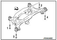
• To install mounting bolts of the suspension member, temporarily tighten them in numerical order shown in the figure and tighten them to the specified torque.
: Vehicle front
• Perform the final tightening of each parts removed when removing rear suspension assembly under unladen conditions.
• Perform inspection after installation. Refer to RSU-36, "Inspection".
Inspection
INSPECTION AFTER REMOVAL
Check rear suspension member for deformation, cracks, or any other damage. Replace it if necessary.
INSPECTION AFTER INSTALLATION
1. Check wheel sensor harness for proper connection. Refer toBRC-85, "REAR WHEEL SENSOR : Exploded View" (Without ESP), BRC-225, "REAR WHEEL SENSOR : Exploded View" (With ESP).
2. Check wheel alignment. Refer to RSU-20, "Inspection".
3. Adjust neutral position of steering angle sensor. Refer to BRC-149, "Work Procedure" (With ESP).
 Rear stabilizer
Exploded View
1. Stabilizer bar
2. Bushing
3. Stabilizer clamp
4. Stabilizer link
5. Lower link
6. Rear suspension member
: Vehicle front
: Always replace after every
disassembly.
: N ...

Other materials:
Basic inspection
DIAGNOSIS AND REPAIR WORKFLOW
Work Flow
OVERALL SEQUENCE
DETAILED FLOW
1.INTERVIEW FOR MALFUNCTION
Interview the symptom to the customer.
>> GO TO 2.
2.SYMPTOM CHECK
Check the symptom from the customer's information.
>> GO TO 3.
3.BASIC INSPECTION
Check the operation o ...
Final drive
Exploded View
1. Shim
2. Differential side bearing outer race
(transaxle case side)
3. Differential side bearing inner race
(transaxle case side)
4. Final gear
5. Differential case
6. Differential side bearing inner race
(clutch housing side)
7. Differential side bearing outer race
( ...
IPDM-E branch line circuit
Diagnosis Procedure
1.CHECK CONNECTOR
1. Turn the ignition switch OFF.
2. Disconnect the battery cable from the negative terminal.
3. Check the terminals and connectors of the IPDM E/R for damage, bend and loose
connection (unit side
and connector side).
Is the inspection result normal?
Y ...
