Nissan Juke Service and Repair Manual : Rear shock absorber
Exploded View
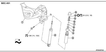
1. Suspension arm
2. Shock absorber
3. Bound bumper
4. Bound bumper cover
5. Washer
6. Bushing
7. Distance tube
8. Piston rod lock nut
9. Cap
 : Vehicle front
 : Always replace after every
disassembly.
 : N·m (kg-m, ft-lb)
Removal and Installation
REMOVAL
1. Remove tires. Refer to WT-7, "Removal and Installation".
2. Set suitable jack under suspension arm.
CAUTION:
• Never damage the suspension arm with a jack.
• Check the stable condition when using a jack.
3. Remove shock absorber mounting bolt and nut (lower side).
4. Remove shock absorber mask. Refer to INT-29, "Exploded View".
5. Remove cap.
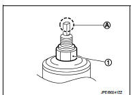
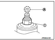
6. Remove piston rod lock nut (1), and then remove washer and bushing.
NOTE
:
To loosen piston rod lock nut, fix the tip (A) of the piston rod.
7. Remove shock absorber assembly.
8. Remove bushing, distance tube, bound bumper cover, and bound bumper from shock absorber.
9. Perform inspection after removal. Refer to RSU-24, "Inspection".
INSTALLATION
Note the following, and install in the reverse order of removal.
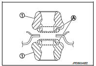
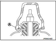
• To install bushings (1), securely insert protrusion (A) into the hole on the vehicle body side.
• Install washer (1) in the direction shown in the figure.
: Bushing side
• Perform final tightening of bolts and nuts at the shock absorber lower side (rubber bussing), under unladen conditions with tires on level ground.
• Hold a head (A) of shock absorber piston rod not to have it rotate, then tighten the piston rod lock nut (1) to the specified torque.
CAUTION:
Never reuse piston rod lock nut.
• When installing the cap, securely engage the cap groove (A) with the flange on the vehicle side.
• Perform inspection after installation. Refer to RSU-24, "Inspection".
• After replacing the shock absorber, always follow the disposal procedure to discard the shock absorber. Refer to RSU-24, "Inspection".
Inspection
INSPECTION AFTER REMOVAL
Shock Absorber
Check the following items, and replace the part if necessary.
• Shock absorber for deformation, cracks, and other damage.
• Piston rod for damage, uneven wear, and distortion.
• Oil leakage
Bound Bumper, Bushing Check for cracks and damage. Replace it if necessary.
Washer, Bound Bumper Cover, Distance Tube • Check for cracks and damage. Replace it if necessary.
INSPECTION AFTER INSTALLATION
Check wheel alignment. Refer to RSU-20, "Inspection".
Disposal
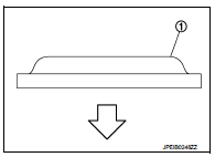
1. Set shock absorber horizontally to the ground with the piston rod fully extracted.
2. Drill 2 – 3 mm (0.08 – 0.12 in) hole at the position (
 ) from top
as shown in the figure to release gas gradually.
CAUTION:
• Wear eye protection (safety glass).
• Wear gloves.
• Be careful with metal chips or oil blown out by the compressed gas.
NOTE:
• Drill vertically in this direction (
 ).
).
• Directly to the outer tube avoiding brackets.
• The gas is clear, colorless, odorless, and harmless.
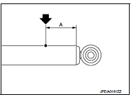
A : 20 – 30 mm (0.79 – 1.18 in)
3. Position the drilled hole downward and drain oil by moving the piston rod several times.
CAUTION:
Dispose of drained oil according to the law and local regulations.

 Coil spring
Exploded View
1. Upper rubber seat
2. Coil spring
3. Lower rubber seat
4. Suspension arm
: Vehicle front
Removal and Installation
REMOVAL
1. Remove tires. Refer to WT-7, "Removal and ...
Other materials:
Integrated control system (if so equipped)
The Integrated Control System is located below the audio system or navigation
system (if so equipped). Two Integrated Control System modes can be selected: Drive
mode and Climate Control mode.
Depending on which Integrated Control System mode selected (Drive mode or Climate
Control mode), the ...
Squeak and rattle trouble diagnoses
Work Flow
CUSTOMER INTERVIEW
Interview the customer if possible, to determine the conditions that exist
when the noise occurs. Use the Diagnostic
Worksheet during the interview to document the facts and conditions when the
noise occurs and any of
the customer's comments; refer to DLK-437, ...
Outside key antennA
Driver side
DRIVER SIDE : Removal and Installation
REMOVAL
Remove the driver side outside handle. Refer to DLK-339, "OUTSIDE HANDLE :
Removal and Installation".
INSTALLATION
Install in the reverse order of removal.
Passenger side
PASSENGER SIDE : Removal and Installation
REMOVA ...
