Nissan Juke Service and Repair Manual : Push-button ignition switch position indicator
Description
Push-button ignition switch changes the power supply position.
BCM maintains the power supply position status.
BCM changes the power supply position with the operation of the push-button ignition switch.
Component Function Check
1.CHECK FUNCTION
Check push-button ignition switch (“PUSH SWITCH INDICATOR”) in Active Test Mode with CONSULT-III.
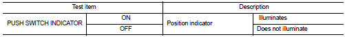
Is the inspection result normal? YES >> INSPECTION END
NO >> Refer to PCS-111, "Diagnosis Procedure".
Diagnosis Procedure
1.CHECK PUSH-BUTTON IGNITION SWITCH INPUT SIGNAL
1. Turn ignition switch OFF.
2. Disconnect push-button ignition switch connector.
3. Check voltage between push-button ignition switch harness connector and ground.
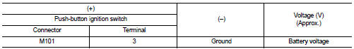
Is the inspection normal? YES >> GO TO 2.
NO-1 >> Check 10 A fuse [No.13, located in fuse block (J/B)].
NO-2 >> Check harness for open or short between push-button ignition switch and fuse.
2.CHECK BCM INPUT
1. Connect push-button ignition switch connector.
2. Disconnect BCM connector.
3. Check voltage between BCM connector and ground.
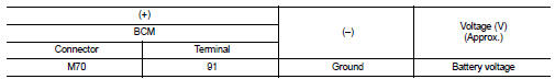
Is the inspection normal? YES >> Replace BCM. Refer to BCS-93, "Removal and Installation".
NO >> GO TO 3.
3.CHECK PUSH-BUTTON IGNITION SWITCH CIRCUIT
1. Disconnect push-button ignition switch connector.
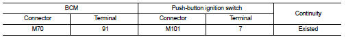
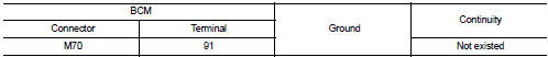
2. Check continuity between BCM harness connector and push-button ignition switch harness connector.
3. Check continuity between BCM harness connector and ground.
Is the inspection normal? YES >> Replace push-button ignition switch.
NO >> Repair or replace harness.
 Push-button ignition switch
Component Function Check
1.CHECK FUNCTION
1. Select “PUSH SW” in “Data Monitor” mode with CONSULT-III.
2. Check the push-button ignition switch signal under the following conditions.
Is the indi ...

Other materials:
Exploded View
1. Main muffler
2. Mounting rubber
3. Ring gasket
4. Center tube
5. Exhaust gas temperature sensor 2
6. Diesel particulate filter assembly
7. Gasket
8. Stud bolt
9. Diesel particulate filter inlet tube
10. Gasket
A. To exhaust manifold
B. To pressure hose
: N·m (kg-m, ft-lb)
: ...
P0643 sensor power supply
DTC Logic
DTC DETECTION LOGIC
DTC CONFIRMATION PROCEDURE
1.PRECONDITIONING
If DTC Confirmation Procedure has been previously conducted, always perform
the following procedure
before conducting the next test.
1. Turn ignition switch OFF and wait at least 10 seconds.
2. Turn ignition swit ...
Power door lock system
System Diagram
System Description
DOOR LOCK FUNCTION
• The door lock and unlock switch (driver side) is build into power window
main switch.
• The door lock and unlock switch (passenger side) is build into front power
window switch (passenger side).
• Interlocked with the locking operatio ...
