Nissan Juke Service and Repair Manual : Primary speed sensor
Exploded View
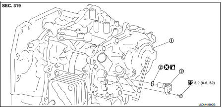
1. Transaxle assembly
2. O-ring
3. Primary speed sensor
 : Always replace after every
disassembly.
 : N m (kg-m, in-lb)
 : Genuine NISSAN CVT Fluid NS-2
Removal and Installation
REMOVAL
1. Remove the battery. Refer to PG-124, "Removal and Installation".
2. Remove the air cleaner case. Refer to EM-161, "Removal and Installation".
3. Remove the ECM and bracket as a set.
4. Disconnect the primary speed sensor connector.
5. Remove the primary speed sensor.
6. Remove the O-ring from the primary speed sensor.
INSTALLATION
Note the following, and install in the reverse order of removal.
CAUTION:
• Never reuse O-ring.
• Apply Genuine NISSAN CVT Fluid NS-2 to the O-ring.
Inspection and Adjustment
INSPECTION AFTER INSTALLATION Check for CVT fluid leakage. Refer to TM-480, "Inspection".
ADJUSTMENT AFTER INSTALLATION Adjust the CVT fluid level. Refer to TM-379, "Adjustment".
 Oil pan
Exploded View
1. Transaxle assembly
2. Oil pan gasket
3. Magnet
4. Oil pan
5. Overflow tube
6. Drain plug gasket
7. Drain plug
8. Oil pan fitting bolt
: Always replace after every
di ...
 Secondary speed sensor
Exploded View
1. Transaxle assembly
2. O-ring
3. Secondary speed sensor
: Vehicle front
: Always replace after every
disassembly.
: N·m (kg-m, in-lb)
: Genuine NISSAN CVT Fluid NS-2
Remo ...
Other materials:
Rear suspension beam
Exploded View
1. Rear suspension beam
2. Rear suspension arm bracket
: Always replace after every
disassembly.
: N·m (kg-m, ft-lb)
Removal and Installation
REMOVAL
1. Remove tires. Refer to WT-7, "Removal and Installation".
2. Drain brake fluid. Refer to BR-12, "Draining& ...
LAN System can system (type 8)
DTC/CIRCUIT DIAGNOSIS
Main line between IPDM-E and DLC circuit
Diagnosis Procedure
1.CHECK CONNECTOR
1. Turn the ignition switch OFF.
2. Disconnect the battery cable from the negative terminal.
3. Check the following terminals and connectors for damage, bend and loose
connection (connector s ...
P1650 thermoplunger control unit
DTC Logic
DTC DETECTION LOGIC
Diagnosis Procedure
1.CHECK THERMOPLUNGER CONTROL UNIT POWER SUPPLY CIRCUIT
1. Turn ignition switch OFF.
2. Disconnect thermoplunger control unit harness connector.
3. Check the voltage between thermoplunger control unit harness connector and
ground.
Is the ...
