Nissan Juke Service and Repair Manual : Power supply and ground circuit
Diagnosis Procedure
1.INSPECTION START
Start engine.
Is engine running? YES >> GO TO 6.
NO >> GO TO 2.
2.CHECK GROUND CONNECTION-I
1. Turn ignition switch OFF.
2. Check ground connection E38. Refer to Ground Inspection in GI-44, "Circuit Inspection".
Is the inspection result normal? YES >> GO TO 3.
NO >> Repair or replace ground connection.
3.CHECK ECM POWER SUPPLY CIRCUIT-I
1. Turn ignition switch ON.
2. Check the voltage between ECM harness connector and ground.
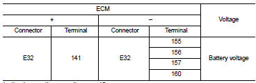
Is the inspection result normal? YES >> GO TO 5.
NO >> GO TO 4.
4.DETECT MALFUNCTIONING PART
Check the following.
• Harness connectors M77, E105
• 10A fuse (No. 2)
• Harness for open or short between ECM and fuse
>> Repair open circuit or short to ground or short to power in harness or connectors.
5.CHECK ECM GROUND CIRCUIT FOR OPEN AND SHORT-I
1. Disconnect ECM harness connectors.
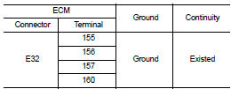
2. Check the continuity between ECM harness connector and ground.
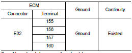
3. Also check harness for short to power.
Is the inspection result normal? YES >> GO TO 6.
NO >> Repair open circuit or short to power in harness or connectors.
6.CHECK ECM POWER SUPPLY CIRCUIT-II
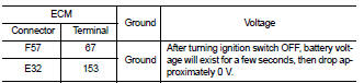
1. Turn ignition switch OFF and wait at least 10 seconds.
2. Check the voltage between ECM harness connector and ground.
Is the inspection result normal? YES >> GO TO 13.
NO-1 >> Battery voltage does not exist: GO TO 7.
NO-2 >> Battery voltage exists for more than a few seconds: GO TO 10.
7.CHECK ECM POWER SUPPLY CIRCUIT-III
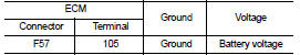
1. Turn ignition switch OFF and wait at least 10 seconds.
2. Check the voltage between ECM harness connector and ground.
Is the inspection result normal? YES >> GO TO 8.
NO >> GO TO 10.
8.CHECK ECM POWER SUPPLY CIRCUIT-IV
1. Disconnect ECM harness connector.
2. Disconnect IPDM E/R harness connector.
3. Check the continuity between ECM harness connector and IPDM E/R harness connector.
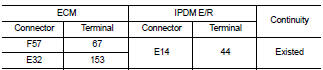
4. Also check harness for short to ground and short to power.
Is the inspection result normal? YES >> GO TO 15.
NO >> GO TO 9.
9.DETECT MALFUNCTIONING PART
Check the following.
• Harness or connectors E8, F1 • Harness for open or short between ECM and IPDM E/R
>> Repair open circuit or short to ground or short to power in harness or connectors.
10.CHECK ECM POWER SUPPLY CIRCUIT-V
1. Disconnect ECM harness connector.
2. Disconnect IPDM E/R harness connector.
3. Check the continuity between ECM harness connector and IPDM E/R harness connector.
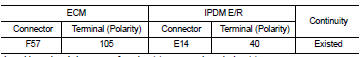
4. Also check harness for short to ground and short to power.
Is the inspection result normal? YES >> GO TO 12.
NO >> GO TO 11.
11.DETECT MALFUNCTIONING PART
Check the following.
• Harness or connectors E8, F1 • Harness for open or short between ECM and IPDM E/R
>> Repair open circuit or short to ground or short to power in harness or connectors.
12.CHECK 20A FUSE
1. Disconnect 20A fuse (No. 43) from IPDM E/R.
2. Check 20A fuse.
Is the inspection result normal? YES >> GO TO 15.
NO >> Replace 20A fuse.
13.CHECK GROUND CONNECTION-II
1. Turn ignition switch OFF.
2. Check ground connection E38. Refer to Ground Inspection in GI-44, "Circuit Inspection".
Is the inspection result normal? YES >> GO TO 14.
NO >> Repair or replace ground connection.
14.CHECK ECM GROUND CIRCUIT FOR OPEN AND SHORT-II
1. Disconnect ECM harness connector.
2. Check the continuity between ECM harness connector and ground.
3. Also check harness for short to power.
Is the inspection result normal? YES >> GO TO 15.
NO >> Repair open circuit or short power in harness or connectors.
15.CHECK INTERMITTENT INCIDENT
Refer to GI-42, "Intermittent Incident", ???INCIDENT SIMULATION TESTS??? and ???GROUND INSPECTION???.
Is the inspection result normal? YES >> Replace IPDM E/R.
NO >> Repair open circuit or short to power in harness or connectors.

 P0001 fuel pump
DTC Logic
DTC DETECTION LOGIC
NOTE:
If DTC P0001 is displayed with DTC P0560 or P0657, first perform trouble
diagnosis for DTC P0560 or P0657.
Refer to EC-963, "DTC Logic" (DTC P05 ...
Other materials:
Additional service when replacing ECM
Description
When replacing ECM, this procedure must be performed.
Work Procedure
1.PRECONDITIONING
• Connect a CONSULT-III
• Connect a battery charger
• Electric load switch is OFF
• Wait for the engine to cool [engine coolant temperature < 60?°C (140?°F) and air
temperature < 50?°C ( ...
P1586 G sensor
DTC Logic
DTC DETECTION LOGIC
DTC CONFIRMATION PROCEDURE
CAUTION:
Be careful of the driving speed.
1.PREPARATION BEFORE WORK
If another "DTC CONFIRMATION PROCEDURE" occurs just before, turn ignition
switch OFF and wait for at
least 10 seconds, then perform the next test.
> ...
Liquid Gasket
REMOVAL OF LIQUID GASKET
• After removing mounting nuts and bolts, separate the mating surface
using the seal cutter [SST: KV10111100] (A) and remove old
liquid gasket sealing.
CAUTION:
Be careful not to damage the mating surfaces.
• Tap the seal cutter [SST: KV10111100] to insert it (B), an ...
