Nissan Juke Service and Repair Manual : Power supply and ground circuit
Diagnosis Procedure
1.CHECK FUSE
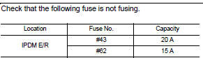
Is the fuse fusing? YES >> Replace the fuse after repairing the applicable circuit.
NO >> GO TO 2.
2.CHECK GROUND CONNECTION
1. Turn ignition switch OFF.
2. Check ground connection E21 and E38. Refer to GI-44, "Circuit Inspection".
Is the inspection result normal? YES >> GO TO 3.
NO >> Repair or replace ground connection.
3.CHECK ECM GROUND CIRCUIT
1. Disconnect ECM harness connectors.
2. Check the continuity between ECM harness connector and ground.
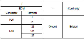
Is the inspection result normal? YES >> GO TO 4.
NO >> Repair or replace error-detected parts.
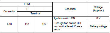
4.CHECK ECM POWER SUPPLY (MAIN)-I
1. Reconnect ECM harness connector.
2. Turn ignition switch ON.
3. Check the voltage between ECM harness connector terminals.
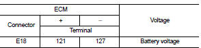
Is the inspection result normal? YES >> GO TO 5.
NO >> GO TO 6.
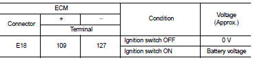
5.CHECK ECM POWER SUPPLY (MAIN)-II
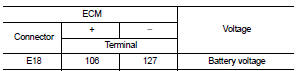
1. Turn ignition switch OFF and wait at least 10 seconds.
2. Check the voltage between ECM harness connector terminals as per the following.
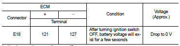
Is the inspection result normal? YES >> GO TO 9.
NO >> GO TO 7.
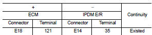
6.CHECK ECM POWER SUPPLY (MAIN) CIRCUIT
1. Turn ignition switch OFF.
2. Disconnect ECM harness connectors.
3. Disconnect IPDM E/R harness connector.
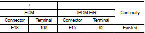
4. Check the continuity between ECM harness connector and IPDM E/R harness connector.
5. Also check harness for short to ground.
Is the inspection result normal? YES >> Perform the trouble diagnosis for power supply circuit.
NO >> Repair or replace error-detected parts.
7.CHECK ECM RELAY CONTROL SIGNAL
Check the voltage between ECM harness connector terminals as per the following.
Is the inspection result normal? YES >> Check Intermittent Incident. Refer to GI-42, "Intermittent Incident".
NO >> GO TO 8.
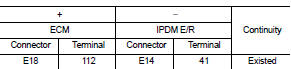
8.CHECK ECM RELAY CONTROL SIGNAL CIRCUIT
1. Turn ignition switch OFF.
2. Disconnect ECM harness connector.
3. Disconnect IPDM E/R harness connector.
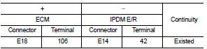
4. Check the continuity between ECM harness connector and IPDM E/R harness connector.
5. Also check harness for short to ground and to power.
Is the inspection result normal? YES >> Replace IPDM E/R. Refer to PCS-34, "Removal and Installation".
NO >> Repair or replace error-detected parts.
9.CHECK IGNITION SWITCH SIGNAL
Is the inspection result normal? YES >> GO TO 11.
NO >> GO TO 10.
10.CHECK IGNITION SWITCH SIGNAL CIRCUIT
1. Turn ignition switch OFF.
2. Disconnect ECM harness connector.
3. Disconnect IPDM E/R harness connector.
4. Check the continuity between ECM harness connector and IPDM E/R harness connector.
5. Also check harness for short to ground and to power.
Is the inspection result normal? YES >> Perform the trouble diagnosis for power supply circuit.
NO >> Repair or replace error-detected parts.
11.CHECK ECM POWER SUPPLY (BACK-UP)
Check the voltage between ECM harness connector terminals.
Is the inspection result normal? YES >> Check Intermittent Incident. Refer to GI-42, "Intermittent Incident".
NO >> GO TO 12.
12.CHECK ECM POWER SUPPLY (BACK-UP) CIRCUIT
1. Turn ignition switch OFF.
2. Disconnect ECM harness connector.
3. Disconnect IPDM E/R harness connector.
4. Check the continuity between ECM harness connector and IPDM E/R harness connector.
5. Also check harness for short to ground.
Is the inspection result normal? YES >> Perform the trouble diagnosis for power supply circuit.
NO >> Repair or replace error-detected parts.
 Trouble diagnosis - specification
value
Trouble diagnosis - specification
value
Description
The specification (SP) value indicates the tolerance of the value that is
displayed in “SPEC” of “DATA MONITOR”
mode of CONSULT-III during normal operation of the Engine Control Syste ...
 U0101 Can comm circuit
Description
CAN (Controller Area Network) is a serial communication line for real time
application. It is an on-vehicle multiplex
communication line with high data communication speed and excelle ...
Other materials:
Engine unit
Disassembly
1. Remove intake manifold. Refer to EM-163, "Exploded View".
2. Remove exhaust manifold. Refer to EM-166, "Exploded View".
3. Remove oil pan (lower). Refer to EM-169, "Exploded View".
4. Remove ignition coil, spark plug, and rocker cover. Refer to EM-17 ...
Chassis maintenance
Headlamp aiming adjustment (halogen type - LHD)
HEADLAMP AIMING ADJUSTMENT (HALOGEN TYPE - LHD) : Description
PREPARATION BEFORE ADJUSTING
NOTE:
• For details, refer to the regulations in your own country.
• Perform aiming if the vehicle front body has been repaired and/or the headlamp
assemb ...
P0444 EVAP canister purge volume
control solenoid valve
DTC Logic
DTC DETECTION LOGIC
DTC CONFIRMATION PROCEDURE
1.CONDITIONING
If DTC Confirmation Procedure has been previously conducted, always perform
the following procedure
before conducting the next test.
1. Turn ignition switch OFF and wait at least 10 seconds.
2. Turn ignition switch ...
