Nissan Juke Service and Repair Manual : Power supply and ground circuit
Diagnosis Procedure
1.CHECK FUSES AND FUSIBLE LINK
Check that the following IPDM E/R fuses or fusible links are not blown.
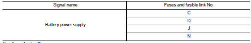
Is the fuse fusing? YES >> Replace the blown fuse or fusible link after repairing the affected circuit if a fuse or fusible link is blown.
NO >> GO TO 2.
2.CHECK POWER SUPPLY CIRCUIT
1. Turn the ignition switch OFF.
2. Disconnect IPDM E/R connector.
3. Check voltage between IPDM E/R harness connector and the ground.
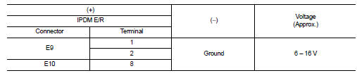
Is the measurement value normal? YES >> GO TO 3.
NO >> Repair the harness or connector.
3.CHECK GROUND CIRCUIT
Check continuity between IPDM E/R harness connectors and the ground.
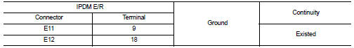
Does continuity exist? YES >> INSPECTION END
NO >> Repair the harness or connector.
 B2099 ignition relay off stuck
Description
• IPDM E/R operates the ignition relay when it receives an ignition switch ON
signal from BCM via CAN communication.
• Turn the ignition relay OFF by pressing the push-button ignition ...
 Removal and installation
IPDM E/R
Exploded View
1. IPDM E/R cover A
2. IPDM E/R
3. IPDM E/R cover B
Removal and Installation
CAUTION:
IPDM E/R integrated relays are not serviceable parts, and must not be removed
...
Other materials:
Hood lock
Exploded View
1. Hood lock control cable assembly
2. Hood lock assembly
: Clip
: N·m (kg-m, ft-lb)
: Body grease
Hood lock
HOOD LOCK : Removal and Installation
REMOVAL
1. Remove front center grille. Refer to EXT-18, "Removal and Installation".
2. Remove crash zone sensor. Refe ...
Door lock status indicator does not illuminate
Diagnosis Procedure
1.CHECK DOOR LOCK STATUS INDICATOR
Check door lock status indicator.
Refer to DLK-395, "Component Function Check".
Is the inspection result normal?
YES >> GO TO 2.
NO >> Repair or replace the malfunctioning parts.
2.REPLACE BCM
1. Replace BCM ...
Steering switch signal A circuit
Description
Transmits the steering switch signal to NAVI control unit.
Diagnosis Procedure
1.CHECK STEERING SWITCH SIGNAL A CIRCUIT
1. Disconnect NAVI control unit connector and spiral cable connector.
2. Check continuity between NAVI control unit harness connector and spiral cable
harness co ...
