Nissan Juke Service and Repair Manual : Power supply and ground circuit
A/C auto AMP. : Diagnosis Procedure
1.CHECK SYMPTOM
Check symptom (A or B).
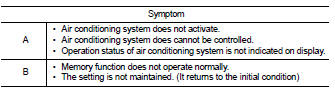
Which symptom is detected? A >>GO TO 2.
B >>GO TO 5.
2.CHECK FUSE
1. Turn ignition switch OFF.
2. Check 10A fuse (No. 3, located in fuse block (J/B)].
NOTE
:
Refer to PG-22, "Fuse, Connector and Terminal Arrangement".
Is the inspection result normal? YES >> GO TO 3.
NO >> Replace the blown fuse after repairing the affected circuit if a fuse is blown.
3.CHECK A/C AUTO AMP. IGNITION POWER SUPPLY
1. Disconnect A/C auto amp. connector.
2. Turn ignition switch ON.
3. Check voltage between A/C auto amp. harness connector and ground.
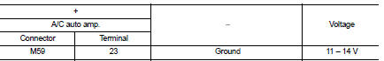
Is the inspection result normal? YES >> GO TO 4.
NO >> Repair harness or connector between A/C auto amp. and fuse.
4.CHECK A/C AUTO AMP. GROUND CIRCUIT FOR OPEN
1. Turn ignition switch OFF.
2. Check continuity between A/C auto amp. harness connector and ground.
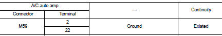
Is the inspection result normal? YES >> Replace A/C auto amp. Refer to HAC-188, "Removal and Installation".
NO >> Repair harness or connector.
5.CHECK FUSE
1. Turn ignition switch OFF.
2. Check 10A fuse (No.7, located in fuse block (J/B)].
NOTE
:
Refer to PG-22, "Fuse, Connector and Terminal Arrangement".
Is the inspection result normal? YES >> GO TO 6.
NO >> Replace the blown fuse after repairing the affected circuit if a fuse is blown.
6.CHECK A/C AUTO AMP. BATTERY POWER SUPPLY
1. Disconnect A/C auto amp. connector.
2. Check voltage between A/C auto amp. harness connector and ground.
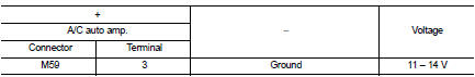
Is the inspection result normal? YES >> Replace A/C auto amp. Refer to HAC-188, "Removal and Installation".
NO >> Repair harness or connector between A/C auto amp. and fuse.
 B27B0 A/C auto AMP.
DTC Logic
DTC DETECTION LOGIC
NOTE:
• If DTC is displayed along with DTC U1000, first perform the trouble diagnosis
for DTC U1000. Refer to HAC-
141, "DTC Logic".
• If DTC is displaye ...
 Door motor
Diagnosis Procedure
NOTE:
If all of door motor DTCs are detected, check this circuit.
1.CHECK DOOR MOTOR POWER SUPPLY
1. Turn ignition switch ON.
2. Check voltage between intake door motor harn ...
Other materials:
Inside key antenna
Instrument center
INSTRUMENT CENTER : Removal and Installation
REMOVAL
1. Remove the multi display unit. Refer to AV-125, "Removal and
Installation".
2. Remove the inside key antenna (instrument center) (1) mounting
clip (A), and then remove inside key antenna (instrument
center).
...
Preparation
Special Service Tools
BASIC INSPECTION
STEERING WHEEL
Inspection
NEUTRAL POSITION STEERING WHEEL
1. Make sure that steering gear assembly, steering column assembly and
steering wheel are installed in the
correct position.
2. Perform neutral position inspection after wheel alignment. Refer ...
P2120 APP sensor
DTC Logic
DTC DETECTION LOGIC
Diagnosis Procedure
1.CHECK GROUND CONNECTIONS
1. Turn ignition switch OFF.
2. Check ground connection E38. Refer to Ground inspection in GI-44, "Circuit
Inspection".
Is the inspection result normal?
YES >> GO TO 2.
NO >> Repair or ...
