Nissan Juke Service and Repair Manual : Power supply and ground circuit
A/C auto AMP. : Diagnosis Procedure
1.CHECK SYMPTOM
Check symptom (A or B).
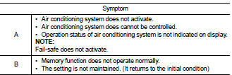
Which symptom is detected? A >> GO TO 2.
B >> GO TO 5.
2.CHECK FUSE
1. Turn ignition switch OFF.
2. Check 10A fuse (No. 3).
NOTE
:
Refer to PG-23, "Fuse and Fusible Link Arrangement".
Is the inspection result normal? YES >> GO TO 3.
NO >> Replace the blown fuse after repairing the affected circuit if a fuse is blown.
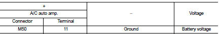
3.CHECK A/C AUTO AMP. IGNITION POWER SUPPLY
1. Disconnect A/C auto amp. connector.
2. Turn ignition switch ON.
3. Check voltage between A/C auto amp. harness connector and ground.
Is the inspection result normal? YES >> GO TO 4.
NO >> Repair harness or connector between A/C auto amp. and fuse.
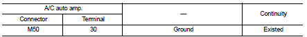
4.CHECK A/C AUTO AMP. GROUND CIRCUIT FOR OPEN
1. Turn ignition switch OFF.
2. Check continuity between A/C auto amp. harness connector and ground.
Is the inspection result normal? YES >> Replace A/C auto amp. Refer to HAC-91, "Removal and Installation".
NO >> Repair harness or connector.
5.CHECK FUSE
1. Turn ignition switch OFF.
2. Check 10A fuse (No.7, located in fuse block (J/B)].
NOTE
:
Refer to PG-22, "Fuse, Connector and Terminal Arrangement".
Is the inspection result normal? YES >> GO TO 6.
NO >> Replace the blown fuse after repairing the affected circuit if a fuse is blown.
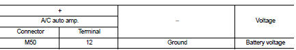
6.CHECK A/C AUTO AMP. BATTERY POWER SUPPLY
1. Disconnect A/C auto amp. connector.
2. Check voltage between A/C auto amp. harness connector and ground.
Is the inspection result normal? YES >> Replace A/C auto amp. Refer to HAC-91, "Removal and Installation".
NO >> Repair harness or connector between A/C auto amp. and fuse.
 B27A6, B27A7, B27A8, B27A9 mode door motor
DTC Logic
DTC DETECTION LOGIC
NOTE:
• If DTC is displayed along with DTC U1000, first perform the trouble diagnosis
for DTC U1000. Refer to HAC-
51, "DTC Logic".
• If DTC is displayed ...
 A/C on signal
Component Function Check
1.CHECK A/C ON SIGNAL
With CONSULT-III
1. Turn ignition switch ON.
2. Operate blower motor.
3. Select “AIR CONDITIONER” of “BCM” using CONSULT-III.
4. Select “AIR COND S ...
Other materials:
Back door opener actuator
Diagnosis Procedure
1.CHECK BACK DOOR OPENER ACTUATOR INPUT SIGNAL
1. Turn ignition switch OFF.
2. Disconnect back door opener assembly connector.
3. Check voltage between back door opener assembly harness connector and ground.
Is the inspection result normal?
YES >> GO TO 3.
NO > ...
General Precautions
• Turn ignition switch OFF and disconnect the battery cable
from the negative terminal before connecting or disconnecting
the CVT assembly harness connector. Because battery
voltage is applied to TCM even if ignition switch is turned
OFF.
• When connecting or disconnecting pin connectors into ...
Refrigerant pressure sensor
Component Function Check
1.CHECK REFRIGERANT PRESSURE SENSOR OVERALL FUNCTION
1. Start engine and warm it up to normal operating temperature.
2. Turn A/C switch and blower fan switch ON.
3. Check the voltage between ECM harness connector and ground.]
Is the inspection result normal?
YES > ...
