Nissan Juke Service and Repair Manual : Power generation voltage variable control system operation inspection
Inspection Procedure
CAUTION:
When performing this inspection, always use a charged battery that has completed
the battery inspection.
(When the charging rate of the battery is low, the response speed of the voltage change will become slow. This can cause an incorrect inspection.)
1.CHECK ECM (CONSULT-III)
Perform ECM self-diagnosis with CONSULT-III. Refer to EC-501, "CONSULT-III Function" (MR16DDT), or EC-835, "CONSULT-III Function" (K9K).
Self-diagnostic results content No malfunction detected>> GO TO 2.
Malfunction detected>> Check applicable parts, and repair or replace corresponding parts.
2.CHECK OPERATION OF POWER GENERATION VOLTAGE VARIABLE CONTROL SYSTEM
1. Connect CONSULT-III and start the engine.
2. Check that the selector lever is in “P” or “N” position and that all of the electric loads and A/C, etc. are turned OFF.
3. Select “ALTERNATOR DUTY” at “Active Test” of “ENGINE”, and then check the value of “BATTERY VOLT” monitor when DUTY value of “ALTERNATOR DUTY” is set to 40.0 %.
“BATTERY VOLT”
2 seconds after setting the
DUTY value of “ALTERNATOR
DUTY” to 40.0 %
: 12 - 13.6 V
4. Check the value of “BATTERY VOLT” monitor when DUTY value of “ALTERNATOR DUTY” is set to 80.0%.
“BATTERY VOLT”
20 seconds after setting
the DUTY value of “ALTERNATOR
DUTY” to 80.0 %
: +0.5 V or more against
the value of “BATTERY
VOLT” monitor when
DUTY value is 40.0 %
Is the measurement value within the specification? YES >> INSPECTION END
NO >> GO TO 3.
3.CHECK IPDM E/R (CONSULT-III)
Perform IPDM E/R self-diagnosis with CONSULT-III. Refer to PCS-14, "CONSULT-III Function (IPDM E/R)" (with Intelligent Key system), PCS-45, "CONSULT-III Function (IPDM E/R)" (without Intelligent Key system).
Self-diagnostic results content
No malfunction detected>> GO TO 4.
Malfunction detected>> Check applicable parts, and repair or replace corresponding parts.
4.CHECK HARNESS BETWEEN ALTERNATOR AND IPDM E/R
1. Turn ignition switch OFF.
2. Disconnect alternator connector and IPDM E/R connector.
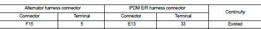
3. Check continuity between alternator harness connector and IPDM E/R harness connector.
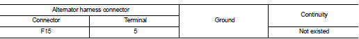
4. Check continuity between alternator harness connector and ground.
Is the inspection result normal? YES >> Replace IPDM E/R.
NO >> Repair harness or connector between IPDM E/R and alternator.
 Charging system preliminary inspection
Inspection Procedure
1.CHECK BATTERY TERMINALS CONNECTION
Check if battery terminals are clean and tight.
Is the inspection result normal?
YES >> GO TO 2.
NO >> Repair battery ter ...

Other materials:
Auto operation does not operate but manual operate normally
(driver side)
Diagnosis Procedure
1.PERFORM INITIALIZATION PROCEDURE
Initialization procedure is executed and operation is confirmed.
Refer to PWC-16, "Work Procedure".
Is the inspection result normal?
YES >> INSPECTION END
NO >> GO TO 2.
2.CHECK ENCODER CIRCUIT
Check encoder c ...
Combination switch output circuit
Diagnosis Procedure
1.CHECK OUTPUT 1 - 5 CIRCUIT FOR OPEN
1. Turn ignition switch OFF.
2. Disconnect BCM and combination switch connectors.
3. Check continuity between BCM harness connector and combination switch harness
connector.
Does continuity exist?
YES >> GO TO 2.
NO >> ...
Wheel alignment
Inspection
DESCRIPTION
Measure wheel alignment under unladen conditions.
NOTE:
“Unladen conditions” means that fuel, engine coolant, and lubricant are full.
Spare tire, jack, hand tools and
mats are in designated positions.
PRELIMINARY CHECK
Check the following:
• Tires for improper ai ...
