Nissan Juke Service and Repair Manual : Parking brake shoe
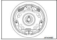
Exploded View
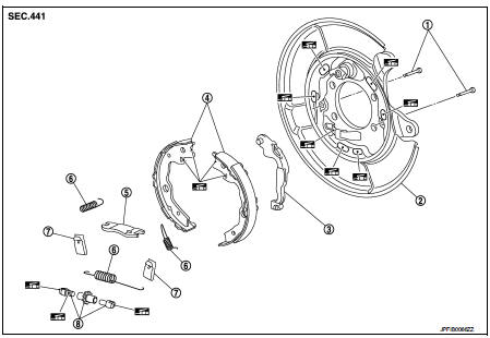
1. Anti-rattle pin
2. Back plate
3. Toggle lever
4. Parking brake shoe
5. Brake strut
6. Return spring
7. Spring
8. Adjuster
 : Apply PBC (Poly Butyl
Cuprysil) grease or silicone-based grease.
Removal and Installation
REMOVAL
WARNING:
Clean any dust from the parking brake shoes and back plates with a vacuum dust
collector. Never
blow with compressed air.
1. Remove rear tires.
2. Remove disc rotor.
• 2WD: Refer to RAX-5, "Removal and Installation".
• 4WD: Refer to RAX-14, "Removal and Installation".
CAUTION:
Parking brake completely in the released position.
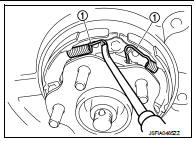
3. Remove return spring (1) of the upper side.
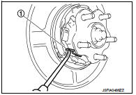
4. Remove return spring (1) of the lower side.
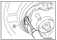
5. Remove spring (1).
CAUTION:
Never drop the removed p
arts.
6. Remove parking brake shoes, adjuster, brake strut and toggle lever.
CAUTION:
• The parking brake shoes for the front wheels are made of
different materials from those for the rear wheels. Never
misidentify them when removing.
• Never drop the removed parts.
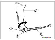
7. Press the rear cable spring (1) against spring tension to remove rear cable (3) from the clamp (A) of toggle lever (2).
CAUTION:
Never bend rear cable
.
8. For the removal of back plate.
• 2WD: Refer to RAX-5, "Removal and Installation".
• 4WD: Refer to RAX-14, "Removal and Installation".
INSTALLATION
Note the following, install in the reverse order of removal.
• Apply PBC (Poly Butyl Cuprysil) grease or silicone-based grease to the back plate and brake shoe.
CAUTION:
The parking brake shoes for the front wheels are made of different materials
from those for the rear
wheels. Never misidentify them when removing and replacing.
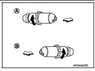
• Assemble adjusters so that threaded part is expanded when rotating it in the direction shown by arrow.
A : For right side brake
B : For left side brake
 : Vehicle front
 : Adjuster expands
• Shorten adjuster by rotating it.
• When disassembling apply PBC (Poly Butyl Cuprysil) grease or silicone- based grease to threads.
• Check that the component parts of the parking brake shoe are properly installed.
• Check brake shoe sliding surface and drum inner surface for grease. Wipe it off if it adhere on the surfaces.
Inspection and Adjustment
INSPECTION AFTER REMOVAL
Lining Thickness Inspection • Check thickness (A) of lining.
A : Refer to PB-11, "Parking Drum Brake".
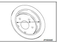
Drum Inner Diameter Inspection • Check inner diameter (B) of drum.
B : Refer to PB-11, "Parking Drum Brake".
Other Inspections
Check the following items, and replace the parts if necessary.
• Lining for excessive wear, damage, and peeling.
• Brake shoe sliding surface for excessive wear and damage.
• Anti-rattle pin for excessive wear, damage and rust.
• Return spring and spring for settling, excessive wear, damage, and rust.
• Adjuster for smoothness.
• Toggle lever and brake strut for excessive wear, damage and rust.
• Visually check inside of the drum for excessive wear, cracks, and damage with a pair of vernier calipers.
ADJUSTMENT AFTER INSTALLATION
1. Adjust the parking brake lever stroke. Refer to PB-2, "Inspection and Adjustment".
2. Rotate the disc rotor to check that there is no drag. Install the plug. If any drag is found, follow the procedure described below.
a. Adjust parking brake stroke again.
b. Check rear disc brake.
• LHD: Refer to BR-68, "BRAKE CALIPER ASSEMBLY : Inspection".
• RHD: Refer to BR-134, "BRAKE CALIPER ASSEMBLY : Inspection".
3. Adjust the parking brake shoe. Refer to PB-3, "Adjustment".
 Parking brake control
Exploded View
2WD
1. Parking brake lever assembly
2. Adjusting nut
3. Parking brake switch
4. Front cable
5. Rear cable (LH)
6. Rear cable (RH)
: Apply multi-purpose grease.
: N·m (kg-m ...
 Service data and specifications (SDS)
Parking Drum Brake
Parking Brake Control
...
Other materials:
Ecu diagnosis information
BCM
Reference Value
VALUES ON THE DIAGNOSIS TOOL
CONSULT-III MONITOR ITEM
TERMINAL LAYOUT
PHYSICAL VALUES
• *1: With manual A/C
• *2: RHD models
• *3: M/T models
• *4: LHD models
• *5: Except M/T models
Fail-safe
FAIL-SAFE CONTROL BY DTC
B ...
High-mounted stop lamp
Exploded View
1. High-mounted stop lamp
2. Seal packing
: N·m (kg-m, in-lb)
Removal and Installation
CAUTION:
Disconnect battery negative terminal or remove the fuse.
REMOVAL
1. Remove blind seal from back door inside.
CAUTION:
Be careful not to damage the blind seal, so that it can b ...
P012B TC boost sensor
DTC Logic
DTC DETECTION LOGIC
Diagnosis Procedure
1.CHECK GROUND CONNECTIONS
1. Turn ignition switch OFF.
2. Check ground connection E38. Refer to Ground inspection in GI-44, "Circuit
Inspection".
Is the inspection result normal?
YES >> GO TO 2.
NO >> Repair or ...
