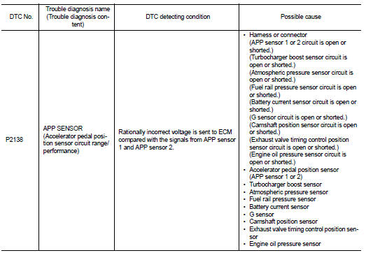
Nissan Juke Service and Repair Manual : P2138 APP sensor
DTC Logic
DTC DETECTION LOGIC
NOTE
:
If DTC P2138 is displayed with DTC P0643, first perform the trouble diagnosis
for DTC P0643. Refer to
EC-307, "DTC Logic".
DTC CONFIRMATION PROCEDURE
1.PRECONDITIONING
If DTC Confirmation Procedure has been previously conducted, always perform the following procedure before conducting the next test.
1. Turn ignition switch OFF and wait at least 10 seconds.
2. Turn ignition switch ON.
3. Turn ignition switch OFF and wait at least 10 seconds.
TESTING CONDITION:
Before performing the following procedure, confirm that battery voltage is more
than 8 V at idle.
>> GO TO 2.
2.PERFORM DTC CONFIRMATION PROCEDURE
1. Start engine and let it idle for 1 second.
2. Check DTC.
Is DTC detected? YES >> Proceed to EC-395, "Diagnosis Procedure".
NO >> INSPECTION END
Diagnosis Procedure
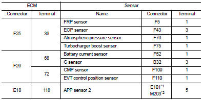
1.CHECK APP SENSOR 1 POWER SUPPLY
1. Turn ignition switch OFF.
2. Disconnect accelerator pedal position (APP) sensor harness connector.
3. Turn ignition switch ON.
4. Check the voltage between APP sensor harness connector and ground.
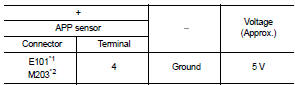
*1: LHD models or RHD with CVT models *2: RHD with M/T models
Is the inspection result normal? YES >> GO TO 3.
NO >> GO TO 2.
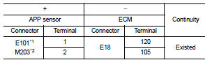
2.CHECK APP SENSOR 1 POWER SUPPLY CIRCUIT
1. Turn ignition switch OFF.
2. Disconnect ECM harness connector.
3. Check the continuity between APP sensor harness connector and ECM harness connector.
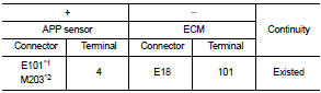
*1: LHD models or RHD with CVT models *2: RHD with M/T models
4. Also check harness for short to ground.
Is the inspection result normal? YES >> Perform the trouble diagnosis for power supply circuit.
NO >> Repair or replace error-detected parts.
3.CHECK APP SENSOR 2 POWER SUPPLY
Check the voltage between APP sensor harness connector and ground.
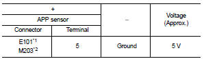
*1: LHD models or RHD with CVT models *2: RHD with M/T models
Is the inspection result normal? YES >> GO TO 5.
NO >> GO TO 4.
4.CHECK SENSOR POWER SUPPLY CIRCUIT
1. Turn ignition switch OFF.
2. Disconnect ECM harness connector.
3. Check harness connector for short to power and short to ground, between the following terminals.
*1: LHD models or RHD with CVT models *2: RHD with M/T models
Is inspection result normal? YES >> Perform the trouble diagnosis for power supply circuit.
NO >> Repair or replace error-detected parts.
5.CHECK APP SENSOR GROUND CIRCUIT
1. Turn ignition switch OFF.
2. Disconnect ECM harness connector.
3. Check the continuity between APP sensor harness connector and ECM harness connector.
*1: LHD models or RHD with CVT models *2: RHD with M/T models
4. Also check harness for short to power.
Is the inspection result normal? YES >> GO TO 6.
NO >> Repair or replace error-detected parts.
6.CHECK APP SENSOR INPUT SIGNAL CIRCUIT
1. Check the continuity between APP sensor harness connector and ECM harness connector.
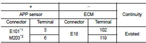
*1: LHD models or RHD with CVT models *2: RHD with M/T models
2. Also check harness for short to ground and to power.
Is the inspection result normal?
YES >> GO TO 7.
NO >> Repair or replace error-detected parts 7.CHECK APP SENSOR
Check the APP sensor. Refer to EC-390, "Component Inspection".
Is the inspection result normal? YES >> Check intermittent incident. Refer to GI-42, "Intermittent Incident".
NO >> Replace accelerator pedal assembly. Refer to EM-28, "Exploded View".
Component Inspection
1.CHECK ACCELERATOR PEDAL POSITION SENSOR
1. Turn ignition switch OFF.
2. Reconnect all harness connectors disconnected.
3. Turn ignition switch ON.
4. Check the voltage between ECM harness connector terminals as per the following condition.
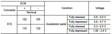
Is the inspection result normal? YES >> INSPECTION END
NO >> Replace accelerator pedal assembly. Refer to EM-28, "Exploded View".
 P2135 TP sensor
DTC Logic
DTC DETECTION LOGIC
NOTE:
If DTC P2135 is displayed with DTC P0643, first perform the trouble diagnosis
for DTC P0643. Refer to
EC-307, "DTC Logic".
DTC CONFIRMATION PROCE ...
 P2162 vehicle speed sensor
Description
ECM receives a rear wheel sensor signal from ABS actuator and electric unit
(control unit) via CAN communication
to switch combustion for the direct injection gasoline system. For the ...
Other materials:
For side and rollover collision : When SRS is not activated in a collision
CAUTION:
Due to varying models and option levels, not all parts listed in the chart below
apply to all vehicles.
WORK PROCEDURE
1. Before performing any of the following steps, ensure that all vehicle body
and structural repairs have been
completed.
2. Check the SRS components and the rel ...
Windshield wiper and washer switch
WARNING
In freezing temperatures the washer solution may freeze on the windshield
and obscure your vision which may lead to an accident. Warm windshield with the
defroster before you wash the windshield.
CAUTION
• Do not operate the washer continuously for more than 30 seconds.
• Do not oper ...
System
Relay control system
RELAY CONTROL SYSTEM : System Diagram
*1: Except for MR16DDT engine models
*2: For MR16DDT engine models
RELAY CONTROL SYSTEM : System Description
IPDM E/R activates the internal control circuit to perform the relay ON-OFF
control according to the input signals
from va ...
