Nissan Juke Service and Repair Manual : P2002 diesel particulate filter
DTC Logic
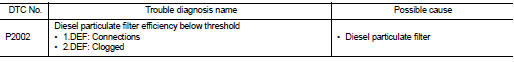
DTC DETECTION LOGIC
Diagnosis Procedure
1.CHECK DIESEL PARTICULATE FILTER
Refer to EC-995, "Component Inspection".
OK or NG OK >> INSPECTION END
NG >> GO TO 2.
2.REPLACE DIESEL PARTICULATE FILTER
1. Replace diesel particulate filter.
2. Perform ???Diesel Particulate Filter Data Clear???. Refer to EC-884, "Work Procedure" >> INSPECTION END
Component Inspection
1.CHECK DIESEL PARTICULATE FILTER-I
1. Start engine and warm it up to normal operating temperature.
2. With engine running in neutral position, make 4 accelerations (wait at least 10 seconds between 2 accelerations).
3. Put white duster on exhaust line output.
4. With engine running in neutral position, make 1 acceleration.
5. Duster is still white.
Is the inspection result normal? YES >> INSPECTION END
NO >> GO TO 2.
2.CHECK DIESEL PARTICULATE FILTER-II
1. Put a new white duster.
2. With engine running in neutral position, make 10 accelerations.
3. Compare duster state with the first one (Step 1 - 5). If duster becames dark grey or black, diesel particulate filter is damaged.
Is the diesel particulate filter damaged? YES >> GO TO 3.
NO >> INSPECTION END
3.REPLACE DIESEL PARTICULATE FILTER
1. Replace diesel particulate filter.
2. Perform ???Diesel Particulate Filter Data Clear???. Refer to EC-884, "Work Procedure".
>> INSPECTION END
 P1650 thermoplunger control unit
DTC Logic
DTC DETECTION LOGIC
Diagnosis Procedure
1.CHECK THERMOPLUNGER CONTROL UNIT POWER SUPPLY CIRCUIT
1. Turn ignition switch OFF.
2. Disconnect thermoplunger control unit harness connector ...
 P2080 EGT sensor 1
DTC Logic
DTC DETECTION LOGIC
Diagnosis Procedure
1.CHECK GROUND CONNECTIONS
1. Turn ignition switch OFF.
2. Check ground connection E38. Refer to Ground inspection in GI-44, "Circuit
In ...
Other materials:
Radiator
Exploded View
1. Reservoir tank cap
2. Reservoir tank
3. Clamp
4. Reservoir tank hose
5. Mounting rubber (upper)
6. Reservoir tank hose
7. Radiator
8. Mounting rubber (lower)
9. Drain plug
10. O-ring
11. Cooling fan assembly
12. Radiator hose (upper)
13. Radiator hose (lower)
...
Can communication circuit
Diagnosis Procedure
1.CONNECTOR INSPECTION
1. Turn the ignition switch OFF.
2. Disconnect the battery cable from the negative terminal.
3. Disconnect all the unit connectors on CAN communication system.
4. Check terminals and connectors for damage, bend and loose connection.
Is the inspectio ...
Precautions for Drive Shaft
• Observe the following precautions when disassembling and assembling drive
shaft.
- Never disassemble joint sub-assembly because it is non-overhaul parts.
- Perform work in a location which is as dust-free as possible.
- Clean the parts, before disassembling and assembling.
- Prevent the entr ...
