Nissan Juke Service and Repair Manual : P1701 TCM
DTC Logic
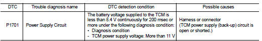
DTC DETECTION LOGIC
DTC CONFIRMATION PROCEDURE
1.PREPARATION BEFORE WORK
If another "DTC CONFIRMATION PROCEDURE" occurs just before, turn ignition switch OFF and wait for at least 10 seconds, then perform the next test.
>> GO TO 2.
2.CHECK DTC DETECTION
1. Start the engine and wait for 5 seconds or more.
2. Check the first trip DTC.
Is “P1701” detected? YES >> Go to TM-440, "Diagnosis Procedure".
NO >> INSPECTION END
Diagnosis Procedure
1.CHECK TCM POWER SUPPLY (BACK-UP) CIRCUIT
1. Turn ignition switch OFF.
2. Disconnect the TCM connector.
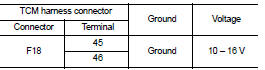
3. Check the voltage between the TCM harness connector terminals and ground.
Is the inspection result normal? YES >> Check intermittent incident. Refer to GI-42, "Intermittent Incident".
NO >> GO TO 2.
2.DETECTION OF MALFUNCTION ITEMS
Check the following items: • Open or short circuit of the harness between battery positive terminal and TCM connectors terminals 45 and 46. Refer to PG-10, "Wiring Diagram - BATTERY POWER SUPPLY -".
• 10A fuse (No.33, fuse and fusible link block). Refer to PG-23, "Fuse and Fusible Link Arrangement".
• 10A fuse (No.36, fuse and fusible link block). Refer to PG-23, "Fuse and Fusible Link Arrangement".
Is the inspection result normal? YES >> Check intermittent incident. Refer to GI-42, "Intermittent Incident".
NO >> Repair or replace the malfunctioning parts.
 P1588 G sensor
DTC Logic
DTC DETECTION LOGIC
DTC CONFIRMATION PROCEDURE
CAUTION:
Be careful of the driving speed.
1.PREPARATION BEFORE WORK
If another "DTC CONFIRMATION PROCEDURE" occurs just befor ...
 P1739 1GR incorrect ratio
DTC Logic
DTC DETECTION LOGIC
DTC CONFIRMATION PROCEDURE
CAUTION:
• Be sure to perform “TM-442, "Diagnosis Procedure"” and then perform “DTC
CONFIRMATION PROCEDURE”.
• Never perform ...
Other materials:
Unit removal and installation
Engine assembly
Exploded View
1. Engine mounting assembly (RH)
2. Rear engine mounting bracket
3. Rear torque rod
4. Engine mounting bracket (LH)
5. Stud bolt
6. Engine mounting bracket (LH)
7. Engine mounting insulator (LH)
8. Mass damper
: N·m (kg-m, ft-lb)
CAUTION:
Check that ...
Ecu diagnosis information
BCM
Reference Value
VALUES ON THE DIAGNOSIS TOOL
CONSULT-III MONITOR ITEM
TERMINAL LAYOUT
PHYSICAL VALUES
• *1: With manual A/C
• *2: RHD models
• *3: M/T models
• *4: LHD models
• *5: Except M/T models
Fail-safe
FAIL-SAFE CONTROL BY DTC
B ...
Unit removal and installation
Transaxle assembly
Exploded View
1. CVT fluid level gauge
2. CVT fluid charging pipe
3. O-ring
4. Transaxle assembly
5. Air breather hose
A. For tightening torque, refer to TM-301, "Removal and Installation".
Removal and Intallation
REMOVAL
WARNING:
Never remove the reservo ...
