Nissan Juke Service and Repair Manual : P1650 thermoplunger control unit
DTC Logic
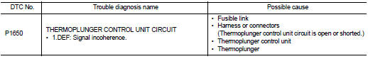
DTC DETECTION LOGIC
Diagnosis Procedure
1.CHECK THERMOPLUNGER CONTROL UNIT POWER SUPPLY CIRCUIT
1. Turn ignition switch OFF.
2. Disconnect thermoplunger control unit harness connector.
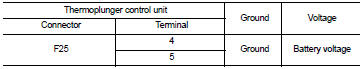
3. Check the voltage between thermoplunger control unit harness connector and ground.
Is the inspection result normal? YES >> GO TO 3.
NO >> GO TO 2.
2.DETECT MALFUNCTIONING PART
Check the following.
• 100A fusible link (letter B) • Harness for open and short between thermoplunger control unit and battery
>> Repair open circuit or short to ground or short to power in harness or connectors.
3.CHECK THERMOPLUNGER CONTROL UNIT SIGNAL CIRCUIT FOR OPEN AND SHORT-I
1. Disconnect ECM harness connector.
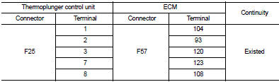
2. Check the continuity between thermoplunger control unit harness connector and ECM harness connector.
3. Also check harness for short to ground and short to power.
Is the inspection result normal? YES >> GO TO 5.
NO >> GO TO 4.
4.DETECT MALFUNCTIONING PART
Check the following.
• Harness for open or short between thermoplunger control unit and ECM.
>> Repair open circuit or short to ground or short to power in harness or connectors.
5.CHECK THERMOPLUNGER CONTROL UNIT SIGNAL CIRCUIT FOR OPEN AND SHORT-II
1. Disconnect thermoplunger harness connector.
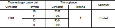
2. Check the continuity between thermoplunger control unit harness connector and thermoplunger harness connector.
3. Also check harness for short to ground and short to power.
Is the inspection result normal? YES >> GO TO 6.
NO >> Repair open circuit or short to ground or short to power in harness or connectors.
6.CHECK THERMOPLUNGER
Refer to EC-994, "Component Inspection".
Is the inspection result normal? YES >> GO TO 7.
NO >> Replace malfunctioning Thermoplunger.
7.CHECK INTERMITTENT INCIDENT
Refer to GI-42, "Intermittent Incident".
Is the inspection result normal? YES >> Replace thermoplunger control unit.
NO >> Repair or replace.
Component Inspection
1.CHECK THERMOPLUNGER
1. Turn ignition switch OFF.
2. Disconnect thermoplunger harness connector.
3. Check resistance between thermoplunger terminals as follows.
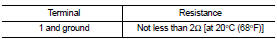
Is the inspection result normal? YES >> INSPECTION END
NO >> Replace malfunctioning thermoplunger.
 P1643 thermoplunger control unit
DTC Logic
DTC DETECTION LOGIC
Diagnosis Procedure
1.CHECK THERMOPLUNGER CONTROL UNIT POWER SUPPLY CIRCUIT
1. Turn ignition switch OFF.
2. Disconnect thermoplunger control unit harness connector ...
 P2002 diesel particulate filter
DTC Logic
DTC DETECTION LOGIC
Diagnosis Procedure
1.CHECK DIESEL PARTICULATE FILTER
Refer to EC-995, "Component Inspection".
OK or NG
OK >> INSPECTION END
NG >> GO TO ...
Other materials:
Push-button ignition switch positions
LOCK (Normal parking position)
The ignition switch can only be locked in this position.
The ignition switch will be unlocked when it is pushed to the ACC position while
carrying the Intelligent Key.
ACC (Accessories)
This position activates electrical accessories such as the radio, when the en ...
Precaution Necessary for Steering Wheel Rotation
after Battery Disconnect
NOTE:
• Before removing and installing any control units, first turn the ignition
switch to the LOCK position, then disconnect
both battery cables.
• After finishing work, confirm that all control unit connectors are connected
properly, then re-connect both
battery cables.
• Always use CONS ...
B1080, B1096 driver air bag module
DTC Logic
DTC DETECTION LOGIC
DTC CONFIRMATION PROCEDURE
1.CHECK SELF-DIAG RESULT
With CONSULT-III
1. Turn ignition switch ON.
2. Perform “Self Diagnostic Result” mode of “AIR BAG” using CONSULT-III.
Without CONSULT-III
1. Turn ignition switch ON.
2. Check the air bag warning lamp statu ...
