Nissan Juke Service and Repair Manual : P1632 fuel cut off valve
DTC Logic
DTC DETECTION LOGIC
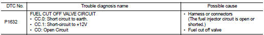
Diagnosis Procedure
1.CHECK FUEL CUT OFF VALVE POWER SUPPLY CIRCUIT FOR OPEN AND SHORT
1. Turn ignition switch OFF.
2. Disconnect fuel cut off valve harness connector.
3. Turn ignition switch ON.
4. Check the voltage between fuel cut off valve harness connector and ground.
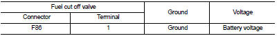
Is the inspection result normal? YES >> GO TO 3.
NO >> GO TO 2.
2.DETECT MALFUNCTIONING PART
Check the following.
• Harness connectors E8, F1 • Harness for open or short between IPDM E/R and fuel cut off valve
>> Repair open circuit or short to ground or short to power in harness or connectors.
3.CHECK FUEL CUT OFF VALVE OUTPUT SIGNAL CIRCUIT FOR OPEN AND SHORT
1. Turn ignition switch OFF.
2. Disconnect ECM harness connector.
3. Check the continuity between fuel cut off valve harness connector and ECM harness connector.
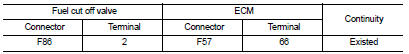
4. Also check harness for short to ground and short to power.
Is the inspection result normal? YES >> GO TO 4.
NO >> Repair open circuit or short to ground or short to power in harness or connectors.
4.CHECK FUEL CUT OFF VALVE
Refer to EC-989, "Component Inspection".
Is the inspection result normal? YES >> GO TO 5.
NO >> Replace exhaust fuel injector.
5.CHECK INTERMITTENT INCIDENT
Refer to GI-42, "Intermittent Incident".
>> INSPECTION END
Component Inspection
1.CHECK FUEL CUT OFF VALVE
1. Turn ignition switch OFF.
2. Disconnect fuel cut off valve harness connector.
3. Check resistance between fuel cut off valve terminals as follows.
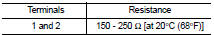
Is the inspection result normal? YES >> INSPECTION END
NO >> Replace fuel cut off valve.
 P160C ECM
DTC Logic
DTC DETECTION LOGIC
Diagnosis Procedure
1.INSPECTION START
1. Turn ignition switch ON.
2. Erase DTC.
3. Turn ignition switch OFF and wait for 20 seconds.
4. Turn ignition switch ON ...
 P1641 thermoplunger control unit
DTC Logic
DTC DETECTION LOGIC
Diagnosis Procedure
1.CHECK THERMOPLUNGER CONTROL UNIT POWER SUPPLY CIRCUIT
1. Turn ignition switch OFF.
2. Disconnect thermoplunger control unit harness connector ...
Other materials:
Auto operation does not operate but manual operate normally
(driver side)
Diagnosis Procedure
1.PERFORM INITIALIZATION PROCEDURE
Initialization procedure is executed and operation is confirmed.
Refer to PWC-16, "Work Procedure".
Is the inspection result normal?
YES >> INSPECTION END
NO >> GO TO 2.
2.CHECK ENCODER CIRCUIT
Check encoder c ...
Diagnosis and repair workflow
Work Flow
OVERALL SEQUENCE
DETAILED FLOW
1.INTERVIEW FOR MALFUNCTION
Interview the symptom to the customer.
>> GO TO 2.
2.SYMPTOM CHECK
Check the symptom from the customer's information.
>> GO TO 3.
3.BASIC INSPECTION
Check the operation of each part. Check that any s ...
Manual Transmission (MT)
WARNING
• Do not downshift abruptly on slippery roads. This may cause a loss
of control.
• Do not over-rev the engine when shifting to a lower gear. This may cause a loss
of control or engine damage.
• When the high fluid temperature protection mode or fail-safe operation occurs,
vehi ...
