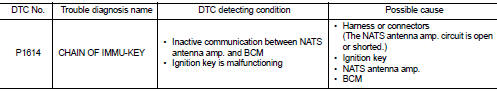
Nissan Juke Service and Repair Manual : P1614 chain of IMMU-KEY
DTC Logic
DTC DETECTION LOGIC
DTC CONFIRMATION PROCEDURE
1.PERFORM DTC CONFIRMATION PROCEDURE
1. Turn ignition switch ON.
2. Check DTC in “Self Diagnostic Result” mode of “ENGINE” using CONSULT-III.
Is DTC detected? YES >> Refer to SEC-195, "Diagnosis Procedure".
NO >> INSPECTION END
Diagnosis Procedure
1.CHECK FUSE
Check that the following IPDM E/R fuse is not blown.

Is the fuse fusing? YES >> Replace the blown fuse after repairing the affected circuit if a fuse is blown.
NO >> GO TO 2.
2.CHECK NATS ANTENNA AMP. INSTALLATION
Check NATS antenna amp. Installation. Refer to SEC-233, "Removal and Installation".
Is the inspection result normal? YES >> GO TO 3.
NO >> Reinstall NATS antenna amp. correctly.
3.CHECK IGNITION KEY
Start engine using another registered ignition key.
Does the engine start? YES-1 >> Replace ignition key.
YES-2 >> Perform initialization of BCM and registration of all ignition keys using CONSULT-III. For initialization and registration procedures, refer to CONSULT-III Operation Manual NATS-IVIS/NVIS.
NO >> GO TO 4.
4.CHECK NATS ANTENNA AMP. POWER SUPPLY
1. Turn ignition switch OFF.
2. Disconnect NATS antenna amp. connector.
3. Check voltage between NATS antenna amp. harness connector and ground.
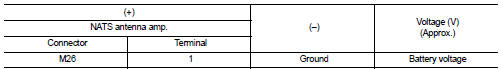
Is the inspection result normal? YES >> GO TO 6.
NO >> GO TO 5.
5.CHECK NATS ANTENNA AMP. POWER SUPPLY CIRCUIT
1. Disconnect IPDM E/R connector.
2. Check continuity between IPDM E/R harness connector and NATS antenna amp. connector.
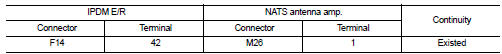
3. Check continuity between IPDM E/R harness connector and ground.
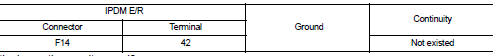
Is the inspection result normal? YES >> Replace IPDM E/R. Refer to PCS-63, "Removal and Installation".
NO >> Repair or replace harness.
6.CHECK NATS ANTENNA AMP. GROUND CIRCUIT
Check continuity between NATS antenna amp. harness connector and ground.
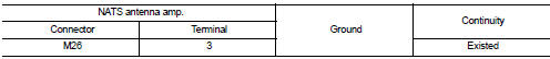
Is the inspection result normal? YES >> GO TO 7.
NO >> Repair or replace harness.
7.CHECK NATS ANTENNA AMP. SIGNAL
1. Connect BCM connector and NATS antenna amp. connector.
2. Check voltage between BCM harness connector and ground.
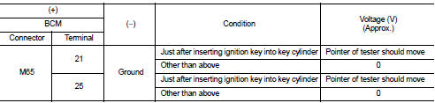
Is the inspection result normal? YES >> GO TO 9.
NO >> GO TO 8.
8.CHECK NATS ANTENNA AMP. SIGNAL CIRCUIT
1. Disconnect NATS antenna amp. connector.
2. Check continuity between BCM harness connector and NATS antenna amp. harness connector.
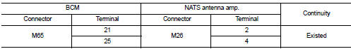
3. Check continuity between BCM harness connector and ground.
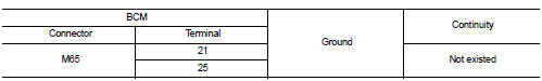
Is the inspection result normal? YES >> Replace NATS antenna amp. Refer to SEC-233, "Removal and Installation".
NO >> Repair or replace harness.
9.CHECK INTERMITTENT INCIDENT
Refer to GI-42, "Intermittent Incident".
>> INSPECTION END
 P1612 chain of ECM-IMMU
DTC Logic
DTC DETECTION LOGIC
NOTE:
• If DTC P1612 is displayed with DTC U1000 (for BCM), first perform the trouble
diagnosis for DTC U1000.
Refer to BCS-153, "DTC Logic".
• If DTC ...
 P1615 diffrence of key
DTC Logic
DTC DETECTION LOGIC
DTC CONFIRMATION PROCEDURE
1.PERFORM DTC CONFIRMATION PROCEDURE
1. Turn ignition switch ON.
2. Check DTC in “Self Diagnostic Result” mode of “ENGINE” using CONSULT ...
Other materials:
P2100, P2103 throttle control motor relay
DTC Logic
DTC DETECTION LOGIC
DTC CONFIRMATION PROCEDURE
1.PRECONDITIONING
If DTC Confirmation Procedure has been previously conducted, always turn
ignition switch OFF and wait at
least 10 seconds before conducting the next test.
TESTING CONDITION:
Before performing the following proced ...
Vehicle Dynamic Control (VDC) system
The Vehicle Dynamic Control (VDC) system uses various sensors to monitor driver
inputs and vehicle motion. Under certain driving conditions, the VDC system helps
to perform the following functions.
• Controls brake pressure to reduce wheel slip on one slipping drive wheel so
power is transfer ...
Clock (if so equipped)
The digital clock (in the audio unit) displays time when the ignition switch
is in the ACC or ON position. The clock ON or OFF mode can be selected. For details
of the digital clock in the NAVIGATION SYSTEM, refer to “Clock” .
If the power supply is disconnected, the clock will not indicate the ...
