Nissan Juke Service and Repair Manual : P159A, P159C, P159D G sensor
For M/T models : DTC Logic
DTC DETECTION LOGIC
DTC CONFIRMATION PROCEDURE
1.PRECONDITIONING
If DTC Confirmation Procedure has been previously conducted, always perform the following procedure before conducting the next test.
1. Turn ignition switch OFF and wait at least 10 seconds.
2. Turn ignition switch ON.
3. Turn ignition switch OFF and wait at least 10 seconds.
TEST CONDITION:
Before performing the following procedure, confirm that battery voltage is more
than 11 V at idle
.
>> GO TO 2.
2.PERFORM DTC CONFIRMATION PROCEDURE
1. Start engine and let it idle for at least 5 seconds.
2. Check 1st trip DTC.
Is 1st trip DTC detected? YES >> Proceed to EC-356, "FOR M/T MODELS : Diagnosis Procedure".
NO >> INSPECTION END
For M/T models : Diagnosis Procedure
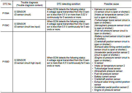
1.CHECK G SENSOR POWER SUPPLY CIRCUIT-I
1. Turn ignition switch OFF.
2. Disconnect G sensor harness connector.
3. Turn ignition switch ON.
4. Check the voltage between G sensor harness connector terminals.
Is the inspection result normal? YES >> GO TO 2.
NO >> GO TO 4.
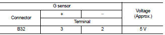
2.CHECK G SENSOR SIGNAL CIRCUIT
1. Turn ignition switch OFF.
2. Disconnect ECM harness connector.
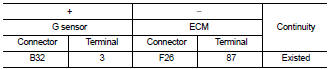
3. Check the continuity between G sensor harness connector and ECM harness connector.
4. Also check harness for short to ground and short to power.
Is the inspection result normal? YES >> GO TO 3.
NO >> Repair or replace error-detected parts.
3.CHECK G SENSOR
Check G sensor. Refer to EC-357, "FOR M/T MODELS : Component Inspection".
Is the inspection result normal? YES >> Check intermittent incident. Refer to GI-42, "Intermittent Incident".
NO >> 1. Replace G sensor. Refer to TM-282, "Exploded View".
2. Perform calibration of G sensor. Refer to EC-138, "Work Procedure".
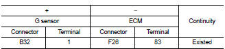
4.CHECK G SENSOR POWER SUPPLY CIRCUIT-II
Check the voltage between G sensor harness connector terminal and ground.
Is the inspection result normal? YES >> GO TO 5.
NO >> GO TO 7.
5.CHECK G SENSOR GROUND CIRCUIT
1. Turn ignition switch OFF.
2. Disconnect ECM harness connector.
3. Check the continuity between G sensor harness connector and ECM harness connector.
Is the inspection result normal? YES >> GO TO 6.
NO >> Repair or replace error-detected parts.
6.CHECK ECM GROUND CIRCUIT
Check the continuity between ECM harness connector and ground.
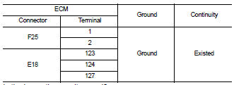
Is the inspection result normal? YES >> Check intermittent incident. Refer to GI-42, "Intermittent Incident".
NO >> Repair or replace error-detected parts.
7.CHECK SENSOR POWER SUPPLY CIRCUIT
1. Turn ignition switch OFF.
2. Disconnect ECM harness connectors and each sensor harness connectors 3. Check harness connector for short to power and short to ground, between the following terminals.
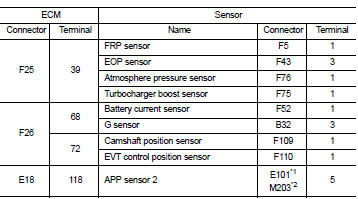
*1: CVT models
*2: RHD with M/T models
Is the inspection result normal? YES >> Perform the trouble diagnosis for power supply circuit.
NO >> Repair or replace error-detected parts.
For M/T models : Component Inspection
1.CHECK G SENSOR
 With CONSULT-III
1. Remove G sensor. Refer to TM-282, "Exploded View".
2. Reconnect all harness connectors disconnected.
3. Place the G sensor on a flat table.
4. Turn ignition switch ON.
5. Select “G SENSOR” in “DATA MONITOR” mode of “ENGINE” using CONSULT-III to check indications according to the following conditions:
 : Direction of gravitational
force
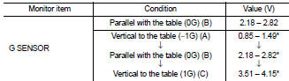
*: Check that voltage rises as the G sensor measurement condition changes in the order of (A), (B), and (C).
Without CONSULT-III
1. Remove G sensor. Refer to TM-282, "Exploded View".
2. Reconnect all harness connectors disconnected.
3. Place the G sensor on a flat table.
4. Turn ignition switch ON.
5. Check the voltage between ECM harness connector terminal and ground.
 : Direction of gravitational
force
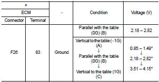
*: Check that voltage rises as the G sensor measurement condition changes in the order of (A), (B), and (C).
Is the inspection result normal? YES >> INSPECTION END
NO >> Replace G sensor. Refer to TM-282, "Exploded View".
 P158A ECM
DTC Logic
*: Since this DTC is detected when G sensor calibration is incomplete, there
is not replacement parts.
1.PRECONDITIONING
If DTC Confirmation Procedure has been previously conducted, ...
 Except for M/T models
Except for M/T models : Description
ECM receives a G sensor signal from TCM via CAN communication to switch
combustion for the direct injection
gasoline system. For the direct injection gasoline s ...
Other materials:
Engine oil
Inspection
ENGINE OIL LEVEL
NOTE:
Before starting engine, put vehicle horizontally and check the engine oil level.
If engine is already started, stop
it and allow 10 minutes before checking.
1. Pull out oil level gauge and wipe it clean.
2. Insert oil level gauge and check that the engine ...
MR16DDT : Inspection and Adjustment
INSPECTION
Magnetic Switch Check
• Before starting to check, disconnect the battery cable from the negative
terminal.
• Disconnect “M” terminal of starter motor.
1. Continuity test [between “S” terminal (A) and switch body]
B : “B” terminal
C : “M” terminal
• Replace magnetic switch if co ...
B2581, B2582 intake sensor
DTC Logic
DTC DETECTION LOGIC
NOTE:
• If DTC is displayed along with DTC U1000, first perform the trouble diagnosis
for DTC U1000. Refer to HAC-
51, "DTC Logic".
• If DTC is displayed along with DTC U1010, first perform the trouble diagnosis
for DTC U1010. HAC-52,
"DTC Logic ...
