Nissan Juke Service and Repair Manual : P1588 G sensor
DTC Logic
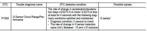
DTC DETECTION LOGIC
DTC CONFIRMATION PROCEDURE
CAUTION:
Be careful of the driving speed.
1.PREPARATION BEFORE WORK
If another "DTC CONFIRMATION PROCEDURE" occurs just before, turn ignition switch OFF and wait for at least 10 seconds, then perform the next test.
>> GO TO 2.
2.CHECK DTC DETECTION
 With CONSULT-III
1. Start the engine.
2. Select “Data Monitor” in “TRANSMISSION”.
3. Select “G SPEED”.
4. Drive the vehicle.
5. Maintain the following conditions for 5 seconds or more.
Selector lever : “D” position G SPEED : 0.05 G or more
6. Stop the vehicle.
7. Check the DTC.
Is “P1588” detected? YES >> Go to TM-438, "Diagnosis Procedure".
NO >> INSPECTION END
Diagnosis Procedure
1.CHECK G SENSOR SIGNAL
 With CONSULT-III
1. Park the vehicle on a level surface.
2. Turn ignition switch ON.
3. Select “Data Monitor” in “TRANSMISSION”.
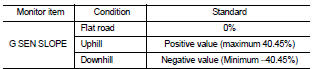
4. Select “G SEN SLOPE”.
5. Swing the vehicle and check if the value varies between −40.45% and 40.45%.
Is the inspection result normal?
YES >> GO TO 2.
NO >> GO TO 3.
2.G SENSOR CALIBRATION (PART 1)
 With CONSULT-III
1. Select “Self Diagnostic Results” in “TRANSMISSION”.
2. Touch “Erase”.
>> Perform "G SENSOR CALIBRATION". Refer to TM-377, "Procedure".
3.CHECK G SENSOR
1. Remove the G sensor. TM-492, "Removal and Installation".
2. Connect the all connectors.
3. Turn ignition switch ON.
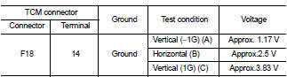
4. Check the voltage between TCM connector terminal and ground.
 : Direction of gravitational
force
Is the inspection result normal? YES >> GO TO 4.
NO >> Replace G sensor.TM-492, "Removal and Installation".
4.G SENSOR CALIBRATION (PART 2)
 With CONSULT-III
1. Install G sensor. TM-492, "Removal and Installation".
2. Select “Self Diagnostic Results” in “TRANSMISSION”.
3. Touch “Erase”.
>> Perform "G SENSOR CALIBRATION". Refer to TM-377, "Procedure".
 P1586 G sensor
DTC Logic
DTC DETECTION LOGIC
DTC CONFIRMATION PROCEDURE
CAUTION:
Be careful of the driving speed.
1.PREPARATION BEFORE WORK
If another "DTC CONFIRMATION PROCEDURE" occurs just befor ...
 P1701 TCM
DTC Logic
DTC DETECTION LOGIC
DTC CONFIRMATION PROCEDURE
1.PREPARATION BEFORE WORK
If another "DTC CONFIRMATION PROCEDURE" occurs just before, turn ignition
switch OFF and wait for a ...
Other materials:
A/C indicator
Diagnosis Procedure
1.CHECK SYMPTOM
Check symptom.
A/C indicator dose not turn ON>>GO TO 2.
A/C indicator dose not turn OFF>>GO TO 6.
2.CHECK FUSE
1. Turn ignition switch OFF.
2. Check 10A fuse (No. 15, located in fuse block (J/B)].
NOTE:
Refer to PG-22, "Fuse, Conn ...
Flat towing
Towing your vehicle with all four wheels on the ground is sometimes called flat
towing. This method is sometimes used when towing a vehicle behind a recreational
vehicle, such as a motor home.
CAUTION
• Failure to follow these guidelines can result in severe transmission damage.
• Whenever fl ...
Basic inspection
Diagnosis and repair workflow
Trouble Diagnosis Flow Chart
Trouble Diagnosis Procedure
INTERVIEW WITH CUSTOMER
Interview with the customer is important to detect the root cause of CAN
communication system errors and to
understand vehicle condition and symptoms for proper trouble diagnosis.
...
