Nissan Juke Service and Repair Manual : P1586 G sensor
DTC Logic
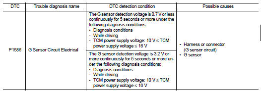
DTC DETECTION LOGIC
DTC CONFIRMATION PROCEDURE
CAUTION:
Be careful of the driving speed.
1.PREPARATION BEFORE WORK
If another "DTC CONFIRMATION PROCEDURE" occurs just before, turn ignition switch OFF and wait for at least 10 seconds, then perform the next test.
>> GO TO 2.
2.CHECK DTC DETECTION
 With CONSULT-III
1. Start the engine.
2. Drive the vehicle for 10 seconds or more.
3. Stop the vehicle.
4. Check the DTC.
Is “P1586” detected? YES >> Go to TM-435, "Diagnosis Procedure".
NO >> INSPECTION END
Diagnosis Procedure
1.CHECK G SENSOR SIGNAL
 With CONSULT-III
1. Park the vehicle on a level surface.
2. Turn ignition switch ON.
3. Select “Data Monitor” in “TRANSMISSION”.
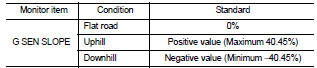
4. Select “G SEN SLOPE”.
5. Swing the vehicle and check if the value varies between −40.45% and 40.45%.
Is the inspection result normal?
YES >> GO TO 2.
NO >> GO TO 3.
2.G SENSOR CALIBRATION (PART 1)
 With CONSULT-III
1. Select “Self Diagnostic Results” in “TRANSMISSION”.
2. Touch “Erase”.
>> Perform "G SENSOR CALIBRATION". Refer to TM-377, "Procedure".
3.CHECK SENSOR POWER SUPPLY
1. Turn ignition switch OFF.
2. Disconnect the G sensor connector.
3. Turn ignition switch ON.
4. Check voltage between G sensor harness connector terminal and ground.
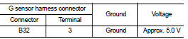
Is the inspection result normal? YES >> GO TO 4.
NO >> GO TO 8.
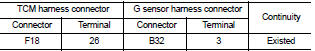
4.CHECK CIRCUIT BETWEEN TCM AND G SENSOR (PART 1)
1. Turn ignition switch OFF.
2. Disconnect the TCM connector.
3. Check continuity between TCM harness connector terminals and G sensor harness connector terminals.
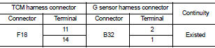
Is the inspection result normal? YES >> GO TO 5.
NO >> Repair or replace the malfunctioning parts.
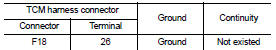
5.CHECK CIRCUIT BETWEEN TCM AND G SENSOR (PART 2)
Check the continuity between TCM harness connector terminals and ground.
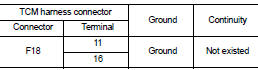
Is the inspection result normal? YES >> GO TO 6.
NO >> Repair or replace the malfunctioning parts.
6.CHECK G SENSOR
1. Remove the G sensor. TM-492, "Removal and Installation".
2. Connect the all connectors.
3. Turn ignition switch ON.
4. Check the voltage between TCM connector terminal and ground.
 : Direction of gravitational
force
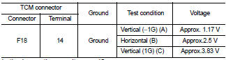
Is the inspection result normal? YES >> GO TO 7.
NO >> Replace G sensor.TM-492, "Removal and Installation".
7.G SENSOR CALIBRATION (PART 2)
With CONSULT-III
1. Install G sensor. TM-492, "Removal and Installation".
2. Select “Self Diagnostic Results” in “TRANSMISSION”.
3. Touch “Erase”.
>> Perform "G SENSOR CALIBRATION". Refer to TM-377, "Procedure".
8.CHECK SENSOR POWER SUPPLY CIRCUIT (PART 1)
1. Turn ignition switch OFF.
2. Disconnect the TCM connector.
3. Check continuity between TCM harness connector terminal and G sensor harness connector terminal.
Is the inspection result normal? YES >> GO TO 9.
NO >> Repair or replace the malfunctioning parts.
9.CHECK SENSOR POWER SUPPLY CIRCUIT (PART 2)
Check the continuity between TCM harness connector terminal and ground.
Is the inspection result normal? YES >> Check intermittent incident. Refer to GI-42, "Intermittent Incident".
NO >> Repair or replace the malfunctioning parts.
 P0963 pressure control solenoid A
DTC Logic
DTC DETECTION LOGIC
DTC CONFIRMATION PROCEDURE
1.PREPARATION BEFORE WORK
If another "DTC CONFIRMATION PROCEDURE" occurs just before, turn ignition
switch OFF and wait for a ...
 P1588 G sensor
DTC Logic
DTC DETECTION LOGIC
DTC CONFIRMATION PROCEDURE
CAUTION:
Be careful of the driving speed.
1.PREPARATION BEFORE WORK
If another "DTC CONFIRMATION PROCEDURE" occurs just befor ...
Other materials:
Key switch
Component Function Check
1.CHECK FUNCTION
1. Select “DOOR LOCK” of “BCM” using CONSULT-III.
2. Select “KEY ON SW” in “DATA MONITOR” mode.
3. Check that the function operates normally according to the following
conditions.
Is the inspection result normal?
YES >> Key switch is OK.
N ...
P1217 engine over temperature
DTC Logic
DTC DETECTION LOGIC
NOTE:
• If DTC P1217 is displayed with DTC UXXXX, first perform the trouble diagnosis
for DTC UXXXX.
• If DTC P1217 is displayed with DTC P0607, first perform the trouble diagnosis
for DTC P0607. Refer
to EC-304, "DTC Logic".
If the cooling fan or ...
Driver side power window does not operate
Diagnosis Procedure
1.CHECK FRONT POWER WINDOW MOTOR (DRIVER SIDE)
Check front power window motor (driver side).
Refer to PWC-26, "DRIVER SIDE : Component Function Check".
Is the inspection result normal?
YES >> GO TO 2.
NO >> Repair or replace the malfunctioning pa ...
