Nissan Juke Service and Repair Manual : P1564 ASCD steering switch
DTC Logic
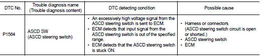
DTC DETECTION LOGIC
NOTE
:
If DTC P1564 is displayed with DTC P0605, first perform the trouble diagnosis
for DTC P0605. Refer to
EC-302, "DTC Logic".
DTC CONFIRMATION PROCEDURE
1.PRECONDITIONING
If DTC Confirmation Procedure has been previously conducted, always perform the following procedure before conducting the next test.
1. Turn ignition switch OFF and wait at least 10 seconds.
2. Turn ignition switch ON.
3. Turn ignition switch OFF and wait at least 10 seconds.
>> GO TO 2.
2.PERFORM DTC CONFIRMATION PROCEDURE
1. Turn ignition switch ON.
2. Wait at least 10 seconds.
3. Press MAIN switch for at least 10 seconds, then release it and wait at least 10 seconds.
4. Press CANCEL switch for at least 10 seconds, then release it and wait at least 10 seconds.
5. Press RES/+ switch for at least 10 seconds, then release it and wait at least 10 seconds.
6. Press SET/− switch for at least 10 seconds, then release it and wait at least 10 seconds.
7. Check DTC.
Is DTC detected? YES >> Proceed to EC-343, "Diagnosis Procedure".
NO >> INSPECTION END
Diagnosis Procedure
1.CHECK ASCD STEERING SWITCH CIRCUIT
 With CONSULT-III
1. Turn ignition switch ON.
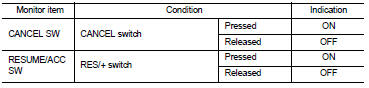
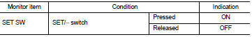
2. Select “CANCEL SW”, “RESUME/ACC SW” and “SET SW” in “DATA MONITOR” mode of “ENGINE” using CONSULT-III.
3. Check each item indication as per the following conditions.
 Without CONSULT-III
1. Turn ignition switch ON.
2. Check the voltage between ECM harness connector terminals.
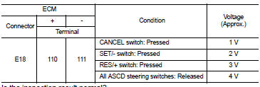
Is the inspection result normal? YES >> Check intermittent incident. Refer to GI-42, "Intermittent Incident".
NO >> GO TO 2.
2.CHECK ASCD STEERING SWITCH GROUND CIRCUIT
1. Turn ignition switch OFF.
2. Disconnect ECM harness connector.
3. Disconnect combination switch (spiral cable) harness connector.
4. Check the continuity between combination switch (spiral cable) and ECM harness connector.
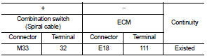
5. Also check harness for short to ground and to power.
Is the inspection result normal? YES >> GO TO 3.
NO >> Repair or replace error-detected parts.
3.CHECK ASCD STEERING SWITCH INPUT SIGNAL CIRCUIT
1. Check the continuity between ECM harness connector and combination switch.
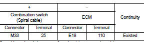
2. Also check harness for short to ground and to power.
Is the inspection result normal? YES >> GO TO 4.
NO >> Repair or replace error-detected parts.
4.CHECK ASCD STEERING SWITCH
Refer to EC-345, "Component Inspection".
Is the inspection result normal?
YES >> Check intermittent incident. Refer to GI-42, "Intermittent Incident".
NO >> Replace ASCD steering switch. Refer to ST-9, "Exploded View".
Component Inspection
1.CHECK ASCD STEERING SWITCH-I
1. Disconnect combination switch (spiral cable) harness connector.
2. Check the continuity between combination switch harness connector terminals as per the following conditions.
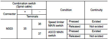
Is the inspection result normal? YES >> INSPECTION END
NO >> Replace ASCD steering switch. Refer to ST-9, "Exploded View".
2.CHECK ASCD STEERING SWITCH
1. Disconnect combination switch (spiral cable) harness connector.
2. Check the resistance between combination switch harness connector terminals as per the following conditions.
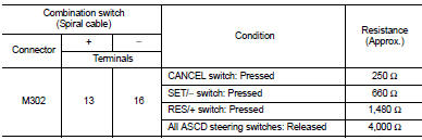
Is the inspection result normal? YES >> INSPECTION END NO >> Replace ASCD steering switch. Refer to ST-9, "Exploded View".
 P1556, P1557 battery temperature
sensor
P1556, P1557 battery temperature
sensor
DTC Logic
DTC DETECTION LOGIC
DTC CONFIRMATION PROCEDURE
1.PRECONDITIONING
1. Turn ignition switch OFF and wait at lest 10 seconds.
2. Turn ignition switch ON.
3. Turn ignition switch OFF and ...
 P1572 ASCD brake switch
DTC Logic
DTC DETECTION LOGIC
NOTE:
• If DTC P1572 is displayed with DTC P0605, first perform the trouble diagnosis
for DTC P0605. Refer
to EC-302, "DTC Logic".
• This self-diagnosis ...
Other materials:
Vehicle jerks during
Description
The vehicle jerks when ABS function and EBD function operates.
Diagnosis Procedure
1.CHECK SYMPTOM
Check that the vehicle jerks when ABS function and EBD function operates.
Is the inspection result normal?
YES >> Normal
NO >> GO TO 2.
2.PERFORM SELF-DIAGNOSIS
Wit ...
Door mirror (open/close motor)
Component Function Check
1.CHECK DOOR MIRROR RETRACT FUNCTION
1. Turn ignition switch ON.
2. Operate open/close switch. Check that door mirror operates normally.
Is the inspection result normal?
YES >> INSPECTION END
NO >> Refer to MIR-25, "Diagnosis Procedure".
Diagno ...
System
System Diagram
System Description
DESCRIPTION
• Manual air conditioning system is controlled by each function of thermo
control amp., BCM, ECM and IPDM
E/R.
• Fan speed of blower motor is changed by the combination of fan control dial
operation and blower fan resistor
control.
CONTROL ...
