Nissan Juke Service and Repair Manual : P1554 battery current sensor
DTC Logic
DTC DETECTION LOGIC
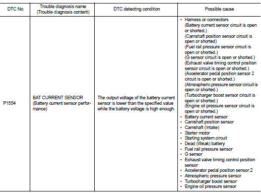
DTC CONFIRMATION PROCEDURE
1.PERFORM COMPONENT FUNCTION CHECK
Perform component function check. Refer to EC-337, "Component Function Check".
NOTE
:
Use component function check to check the overall function of the battery
current sensor circuit. During this
check, a 1st trip DTC might not be confirmed.
Is the inspection result normal? YES >> INSPECTION END
NO >> Proceed to EC-338, "Diagnosis Procedure".
Component Function Check
1.PRECONDITIONING
TESTING CONDITION: • Before performing the following procedure, confirm that battery voltage is more than 12.8 V at idle.
• Before performing the following procedure, confirm that all load switches and A/C switch are turned OFF.
>> GO TO 2.
2.PERFORM COMPONENT FUNCTION CHECK
 With CONSULT-III
1. Start engine and let it idle.
2. Select “BAT CUR SEN” in “DATA MONITOR” mode of “ENGINE” using CONSULT-III.
3. Check “BAT CUR SEN” indication for 10 seconds.
“BAT CUR SEN” should be above 2,300 mV at least once.
 Without CONSULT-III
1. Start engine and let it idle.
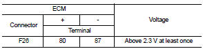
2. Check the voltage between ECM harness connector and ground.
Is the inspection result normal? YES >> INSPECTION END
NO >> Proceed to EC-338, "Diagnosis Procedure".
Diagnosis Procedure
1.CHECK BATTERY CURRENT SENSOR POWER SUPPLY
1. Turn ignition switch OFF.
2. Disconnect battery current sensor harness connector.
3. Turn ignition switch ON.
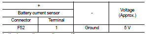
4. Check the voltage between battery current sensor harness connector and ground.
Is the inspection result normal? YES >> GO TO 3.
NO >> GO TO 2.
2.CHECK SENSOR POWER SUPPLY CIRCUIT
1. Turn ignition switch OFF.
2. Disconnect ECM harness connector.
3. Check harness connector for short to power and short to ground, between the following terminals.
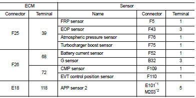
*1: LHD models or RHD with CVT models *2: RHD with M/T models
Is the inspection result normal? YES >> Perform the trouble diagnosis for power supply circuit.
NO >> Repair or replace error-detected parts.
3.CHECK BATTERY CURRENT SENSOR GROUND CIRCUIT
1. Turn ignition switch OFF.
2. Disconnect ECM harness connector.
3. Check the continuity between battery current sensor harness connector and ECM harness connector.
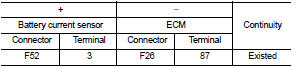
4. Also check harness for short to power.
Is the inspection result normal? YES >> GO TO 4.
NO >> Repair or replace error-detected parts.
4.CHECK BATTERY CURRENT SENSOR INPUT SIGNAL CIRCUIT
1. Check the continuity between battery current sensor harness connector and ECM harness connector.
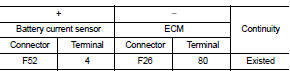
2. Also check harness for short to ground and to power.
Is the inspection result normal? YES >> GO TO 5.
NO >> Repair or replace error-detected parts
5.CHECK BATTERY CURRENT SENSOR
Check the battery current sensor. Refer to EC-330, "Component Inspection".
Is the inspection result normal? YES >> Check intermittent incident. Refer to GI-42, "Intermittent Incident".
NO >> Replace battery negative cable assembly. Refer to PG-125, "Exploded View".
Component Inspection
1.CHECK BATTERY CURRENT SENSOR
1. Turn ignition switch OFF.
2. Reconnect harness connectors disconnected.
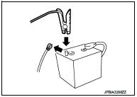
3. Disconnect battery negative cable.
4. Install jumper cable between battery negative terminal and body ground.
5. Turn ignition switch ON.
6. Check the voltage between ECM harness connector and ground.
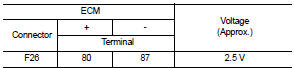
Before measuring the terminal voltage, confirm that the battery is fully charged. Refer to PG-111, "How to Handle Battery".
Is the inspection result normal? YES >> INSPECTION END
NO >> Replace battery negative cable assembly. Refer to PG-125, "Exploded View".
 P1553 battery current sensor
DTC Logic
DTC DETECTION LOGIC
DTC CONFIRMATION PROCEDURE
1.PRECONDITIONING
If DTC Confirmation Procedure has been previously conducted, always perform
the following before conducting
the next ...
 P1556, P1557 battery temperature
sensor
P1556, P1557 battery temperature
sensor
DTC Logic
DTC DETECTION LOGIC
DTC CONFIRMATION PROCEDURE
1.PRECONDITIONING
1. Turn ignition switch OFF and wait at lest 10 seconds.
2. Turn ignition switch ON.
3. Turn ignition switch OFF and ...
Other materials:
Key out interlock door unlock function does not operate
Diagnosis Procedure
1.CHECK “AUTOMATIC LOCK/UNLOCK SELECT” SETTING IN “WORK SUPPORT”
1. Select “DOOR LOCK” of “BCM” using CONSULT-III.
2. Select “AUTOMATIC LOCK/UNLOCK SELECT” in “WORK SUPPORT” mode.
3. Check “AUTOMATIC LOCK/UNLOCK SELECT” in “WORK SUPPORT”.
Refer to DLK-501, "DOOR LOCK ...
P1614 chain of IMMU-KEY
DTC Logic
DTC DETECTION LOGIC
DTC CONFIRMATION PROCEDURE
1.PERFORM DTC CONFIRMATION PROCEDURE 1
1. Contact Intelligent Key backside to push-button ignition switch.
2. Check DTC in “Self Diagnostic Result” mode of “ENGINE” using CONSULT-III.
Is DTC detected?
YES >> Go to SEC-55, &quo ...
Assembly and Installation
• Use torque wrench to tighten bolts or nuts to specification.
• When tightening nuts and bolts, as a basic rule, equally tighten in several
different steps starting with the
ones in center, then ones on inside and outside diagonally in this order. If the
order of tightening is specified,
do ...
