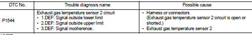
Nissan Juke Service and Repair Manual : P1544 EGT sensor 2
DTC Logic
DTC DETECTION LOGIC
NOTE
:
If DTC P1544 is displayed with DTC P0115, first perform trouble diagnosis for
DTC P0115. Refer to EC-907,
"DTC Logic".
Diagnosis Procedure
1.CHECK GROUND CONNECTIONS
1. Turn ignition switch OFF.
2. Check ground connection E38. Refer to Ground inspection in GI-44, "Circuit Inspection".
Is the inspection result normal? YES >> GO TO 2.
NO >> Repair or replace ground connection.
2.CHECK EXHAUST GAS TEMPERATURE SENSOR 2 POWER SUPPLY CIRCUIT
1. Disconnect exhaust gas temperature sensor 2 harness connector.
2. Turn ignition switch ON.
3. Check the voltage between exhaust gas temperature sensor 2 harness connector and ground.
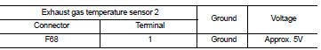
Is the inspection result normal? YES >> GO TO 3.
NO >> Repair open circuit or short to ground or short to power in harness or connectors.
3.CHECK EXHAUST GAS TEMPERATURE SENSOR 2 GROUND CIRCUIT FOR OPEN AND SHORT
1. Turn ignition switch OFF.
2. Disconnect ECM harness connector.
3. Check the continuity between exhaust gas temperature sensor 2 harness connector and ECM harness connector.
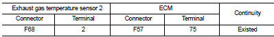
4. Also check harness for short to ground and short to power.
Is the inspection result normal? YES >> GO TO 4.
NO >> Repair open circuit or short to ground or short to power in harness or connectors.
4.CHECK INTERMITTENT INCIDENT
Refer to GI-42, "Intermittent Incident".
Is the inspection result normal? YES >> Replace exhaust gas temperature sensor 2.
NO >> Repair or replace.
 P1525 communication circuit for ASCD and speed limiter
DTC Logic
DTC DETECTION LOGIC
...
 P1545 EGT sensor 2
DTC Logic
DTC DETECTION LOGIC
NOTE:
If DTC P1545 is displayed with DTC P1544, first perform trouble diagnosis for
DTC P1544. Refer to EC-985,
"DTC Logic". ...
Other materials:
Too much power
Description
CHART 13: TOO MUCH POWER
Diagnosis Procedure
1.CHECK ECM POWER SUPPLY AND GROUND CIRCUIT
Check ECM power supply and ground circuit. Refer to EC-885, "Diagnosis
Procedure".
Is the inspection result normal?
YES >> GO TO 2.
NO >> Repair or replace harness ...
Push-button ignition switch position indicator
Description
Push-button ignition switch changes the power supply position.
BCM maintains the power supply position status.
BCM changes the power supply position with the operation of the push-button
ignition switch.
Component Function Check
1.CHECK FUNCTION
Check push-button ignition swi ...
Loading tips
• The GVW must not exceed GVWR or GAWR as specified on the F.M.V.S.S./
C.M.V.S.S. certification label.
• Do not load the front and rear axle to the GAWR. Doing so will exceed the GVWR.
WARNING
• Properly secure all cargo with ropes or straps to help prevent it
from sliding or shif ...
