Nissan Juke Service and Repair Manual : P0850 PNP switch
Description
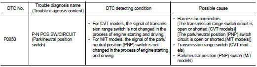
For CVT models, transmission range switch is turn ON when the selector lever is P or N.
For M/T models, park/neutral position (PNP) range switch is ON when the selector lever is Neutral position.
ECM detects the position because the continuity of the line (the ON) exists.
DTC Logic
DTC DETECTION LOGIC
DTC CONFIRMATION PROCEDURE
1.INSPECTION START
Do you have CONSULT-III? Do you have CONSULT-III? YES >> GO TO 2.
NO >> GO TO 5.
2.PRECONDITIONING
If DTC Confirmation Procedure has been previously conducted, always perform the following procedure before conducting the next test.
1. Turn ignition switch OFF and wait at least 10 seconds.
2. Turn ignition switch ON.
3. Turn ignition switch OFF and wait at least 10 seconds.
>> GO TO 3.
3.CHECK PNP SIGNAL FUNCTION
 With CONSULT-III
1. Turn ignition switch ON.
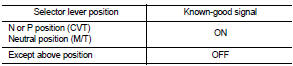
2. Select “P/N POSI SW” in “DATA MONITOR” mode of “ENGINE” using CONSULT-III. Then check the “P/N POSI SW” signal as per the following conditions.
Is the inspection result normal? YES >> GO TO 4.
NO >> Proceed to EC-310, "Diagnosis Procedure".
4.PERFORM DTC CONFIRMATION PROCEDURE
1. Select “DATA MONITOR” mode of “ENGINE” using CONSULT-III.
2. Start engine and warm it up to normal operating temperature.
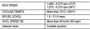
3. Maintain the following conditions for at least 60 consecutive seconds.
CAUTION:
Always drive vehicle at a safe speed.
4. Check 1st trip DTC.
Is 1st trip DTC detected? YES >> Proceed to EC-310, "Diagnosis Procedure".
NO >> INSPECTION END 5.PERFORM COMPONENT FUNCTION CHECK
Perform component function check. Refer to EC-310, "Component Function Check".
NOTE
:
Use component function check the overall function of the transmission range
switch circuit (CVT models) or
the park/neutral position (PNP) switch circuit (M/T models). During this check,
a 1st trip DTC might not be confirmed.
Is the inspection result normal? YES >> INSPECTION END
NO >> Proceed to EC-310, "Diagnosis Procedure".
Component Function Check
1.PERFORM COMPONENT FUNCTION CHECK
1. Turn ignition switch ON.
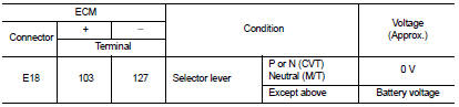
2. Check the voltage between ECM harness connector and ground as per the following conditions.
Is the inspection result normal? YES >> INSPECTION END
NO >> Proceed to EC-310, "Diagnosis Procedure".
Diagnosis Procedure
1.INSPECTION START
Check which type of transmission the vehicle is equipped with.
Which type of transmission? CVT >> GO TO 2.
M/T >> GO TO 6.
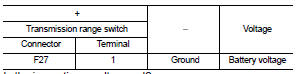
2.CHECK TRANSMISSION RANGE SWITCH POWER SUPPLY
1. Turn ignition switch OFF.
2. Disconnect transmission range switch harness connector.
3. Turn ignition switch ON.
4. Check the voltage between transmission range switch harness connector and ground.
Is the inspection result normal? YES >> GO TO 4.
NO >> GO TO 3.
3.CHECK TRANSMISSION RANGE SWITCH POWER SUPPLY CIRCUIT
1. Turn ignition switch OFF.
2. Disconnect IPDM E/R harness connector.
3. Check the continuity between transmission range switch harness connector and IPDM E/R harness connector.
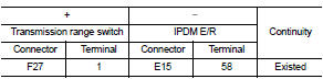
4. Also check harness for short to ground.
Is the inspection result normal? YES >> Perform the trouble diagnosis for power supply circuit.
NO >> Repair or replace error-detected parts.
4.CHECK TRANSMISSION RANGE SWITCH SIGNAL CIRCUIT
1. Turn ignition switch OFF.
2. Disconnect ECM harness connector.
3. Check the continuity between transmission range switch harness connector and ECM harness connector.
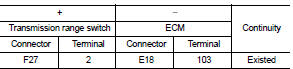
4. Also check harness for short to ground and to power.
Is the inspection result normal? YES >> GO TO 5.
NO >> Repair or replace error-detected parts.
5.CHECK TRANSMISSION RANGE SWITCH
Check the transmission range switch. Refer to TM-201, "Component Inspection".
Is the inspection result normal? YES >> Check intermittent incident. Refer to GI-42, "Intermittent Incident".
NO >> Replace transmission range switch. Refer to TM-278, "Removal and Installation".
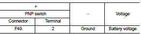
6.CHECK PARK/NEUTRAL POSITION (PNP) SWITCH POWER SUPPLY
1. Turn ignition switch OFF.
2. Disconnect PNP switch harness connector.
3. Turn ignition switch ON.
4. Check the voltage between PNP switch harness connector and ground.
Is the inspection result normal? YES >> GO TO 7.
NO >> Perform the trouble diagnosis for power supply circuit.
7.CHECK PNP SWITCH INPUT SIGNAL CIRCUIT
1. Turn ignition switch OFF.
2. Disconnect ECM harness connector.
3. Check the continuity between PNP switch harness connector and ECM harness connector.
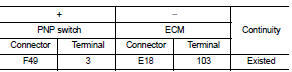
4. Also check harness for short to ground and to power.
Is the inspection result normal? YES >> GO TO 5.
NO >> Repair or replace error-detected parts.
8.CHECK PNP SWITCH
Check the PNP switch. Refer to TM-73, "PARK/NEUTRAL POSITION (PNP) SWITCH : Component Inspection".
Is the inspection result normal? YES >> Check intermittent incident. Refer to GI-42, "Intermittent Incident".
NO >> Replace PNP switch. Refer to TM-77, "Removal and Installation".
 P0643 sensor power supply
DTC Logic
DTC DETECTION LOGIC
DTC CONFIRMATION PROCEDURE
1.PRECONDITIONING
If DTC Confirmation Procedure has been previously conducted, always perform
the following procedure
before conductin ...
 P1078 EVT control position sensor
DTC Logic
DTC DETECTION LOGIC
DTC CONFIRMATION PROCEDURE
1.PRECONDITIONING
If DTC Confirmation Procedure has been previously conducted, always perform
the following procedure
before conductin ...
Other materials:
C1115 wheel sensor
DTC Logic
DTC CONFIRMATION PROCEDURE
1.PRECONDITIONING
If “DTC CONFIRMATION PROCEDURE” has been previously conducted, always turn
ignition switch OFF and
wait at least 10 seconds before conducting the next test.
>> GO TO 2.
2.CHECK DTC DETECTION
With CONSULT-III.
1. Stat the en ...
B210E starter relay
DTC Logic
DTC DETECTION LOGIC
NOTE:
• If DTC B210E is displayed with DTC U1000, first perform the trouble diagnosis
for DTC U1000. Refer to
PCS-59, "DTC Logic".
• If DTC B210E is displayed with DTC B209F, first perform the trouble diagnosis
for DTC B209F. Refer to
SEC-209, " ...
Buzzer (combination meter)
Component Function Check
1.CHECK FUNCTION
1. Select “INTELLIGENT KEY” of “BCM” using CONSULT-III.
2. Select “INSIDE BUZZER” in “ACTIVE TEST” mode.
3. Check that the function operates normally according to the following
conditions.
Is the inspection result normal?
Yes >> Buzzer (combi ...
