Nissan Juke Service and Repair Manual : P0826 up and down shift SW
DTC Logic
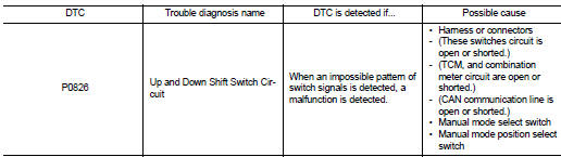
DTC DETECTION LOGIC
DTC CONFIRMATION PROCEDURE
CAUTION:
Always drive vehicle at a safe speed.
NOTE:
If “DTC CONFIRMATION PROCEDURE” has been previously conducted, always turn ignition switch OFF and wait at least 10 seconds before conducting the next test.
After the repair, perform the following procedure to confirm the malfunction is eliminated.
1.CHECK DTC DETECTION
 With CONSULT-III
1. Turn ignition switch ON.
2. Select “DATA MONITOR” in “TRANSMISSION”.
3. Start engine.
4. Drive vehicle for at least 2 consecutive seconds.
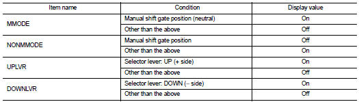
MMODE : ON
Is “P0826” detected? YES >> Go to TM-227, "Diagnosis Procedure".
NO >> Check intermittent incident. Refer to GI-42, "Intermittent Incident".
Diagnosis Procedure
1.CHECK MANUAL MODE SWITCH CIRCUIT
 With CONSULT-III
1. Turn ignition switch ON.
2. Select “DATA MONITOR”.
3. Check the ON/OFF operations of each monitor item.
Without CONSULT-III
Drive the vehicle in the manual mode and shift lever to the “UP (+ side)” or “(− side)” side (1st ⇔ 6th gear).Check that the meter indicator coincides with the actual gear position.
Is the inspection result normal? YES >> GO TO 5.
NO >> GO TO 2.
2.CHECK MANUAL MODE SWITCH
Check manual mode switch. Refer to TM-228, "Component Inspection".
Is the inspection result normal? YES >> GO TO 3.
NO >> Repair or replace damaged parts.
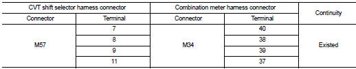
3.CHECK HARNESS BETWEEN CVT SHIFT SELECTOR HARNESS CONNECTOR AND COMBINATION METER HARNESS CONNECTOR
1. Turn ignition switch OFF.
2. Disconnect CVT shift selector harness connector and combination meter harness connector.
3. Check continuity between CVT shift selector harness connector terminals and combination meter harness connector terminals.
4. If OK, check harness for short to ground and short to power.
Is the inspection result normal? YES >> GO TO 4.
NO >> Repair or replace damaged parts.
4.CHECK GROUND CIRCUIT
1. Check continuity between CVT shift selector harness connector terminals and ground.

2. If OK, check harness for short to ground and short to power.
3. Reinstall any part removed.
Is the inspection result normal? YES >> GO TO 5.
NO >> Repair or replace damaged parts.
5.CHECK TCM
Check TCM input/output signals. Refer to TM-164, "Reference Value".
Is the inspection result normal? YES >> Check intermittent incident. Refer to GI-42, "Intermittent Incident".
NO >> Replace the TCM. Refer to TM-280, "Removal and Installation".
Component Inspection
MANUAL MODE SWITCH
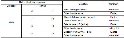
1.MANUAL MODE SWITCH
Check continuity between CVT shift selector connector terminals.
Is the inspection result normal? YES >> INSPECTION END
NO >> Repair or replace damaged parts.
 P0778 pressure control solenoid B
DTC Logic
DTC DETECTION LOGIC
DTC CONFIRMATION PROCEDURE
NOTE:
If “DTC CONFIRMATION PROCEDURE” has been previously performed, always turn
ignition switch
OFF and wait at least 10 seconds befo ...
 P0840 transmission fluid pressure SEN/SW A
DTC Logic
DTC DETECTION LOGIC
DTC CONFIRMATION PROCEDURE
NOTE:
If “DTC CONFIRMATION PROCEDURE” has been previously performed, always turn
ignition switch
OFF and wait at least 10 seconds befo ...
Other materials:
Reporting safety defects
For USA
If you believe that your vehicle has a defect which could cause a crash or could
cause injury or death, you should immediately inform the National Highway Traffic
Safety Administration (NHTSA) in addition to notifying NISSAN.
If NHTSA receives similar complaints, it may open an investi ...
Ignition signal
Component Function Check
1.INSPECTION START
Turn ignition switch OFF, and restart engine.
Does the engine start?
YES-1 >> With CONSULT-III: GO TO 2.
YES-2 >> Without CONSULT-III: GO TO 3.
NO >> Go to EC-783, "Diagnosis Procedure".
2.IGNITION SIGNAL FUNCTION ...
U1000 can comm
Description
CAN (Controller Area Network) is a serial communication line for real time
applications. It is an on-vehicle multiplex
communication line with high data communication speed and excellent error
detection ability. Modern
vehicle is equipped with many electronic control unit, and eac ...
