Nissan Juke Service and Repair Manual : P0715 input speed sensor A
DTC Logic
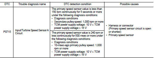
DTC DETECTION LOGIC
DTC CONFIRMATION PROCEDURE
CAUTION:
Be careful of the driving speed.
1.PREPARATION BEFORE WORK
If another "DTC CONFIRMATION PROCEDURE" occurs just before, turn ignition switch OFF and wait for at least 10 seconds, then perform the next test.
>> GO TO 2.
2.CHECK DTC DETECTION
1. Start the engine.
2. Drive the vehicle.
3. Maintain the following conditions for 10 seconds or more.
Selector lever : “L” POSITION Vehicle speed : 40 km/h (25 MPH) or more
4. Stop the vehicle.
5. Check the first trip DTC.
Is “P0715” detected? YES >> Go to TM-410, "Diagnosis Procedure".
NO >> INSPECTION END
Diagnosis Procedure
1.CHECK PRIMARY SPEED SENSOR POWER CIRCUIT
Check voltage between primary speed sensor harness connector terminal and ground.
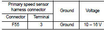
Is the check result normal? YES >> GO TO 6.
NO >> GO TO 2.
2.CHECK PRIMARY SPEED SENSOR GROUND CIRCUIT
Check continuity between primary speed sensor harness connector terminal and ground.
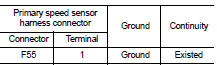
Is the check result normal? YES >> GO TO 3.
NO >> Repair or replace the malfunctioning parts.
3.CHECK CIRCUIT BETWEEN PRIMARY SPEED SENSOR AND TCM (PART 1)
1. Turn ignition switch OFF.
2. Disconnect the TCM connector.
3. Check continuity between primary speed sensor harness connector terminal and TCM harness connector terminal.

Is the check result normal? YES >> GO TO 4.
NO >> Repair or replace the malfunctioning parts.
4.CHECK CIRCUIT BETWEEN PRIMARY SPEED SENSOR AND TCM (PART 1)
Check continuity between primary speed sensor harness connector terminal and ground.
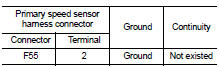
YES >> GO TO 5.
NO >> Repair or replace the malfunctioning parts.
5.CHECK TCM INPUT SIGNALS
1. Connect all of the disconnected connectors.
2. Lift the vehicle.
3. Start the engine.
4. Check frequency of primary speed sensor.
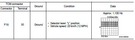
Is the check result normal? YES >> Check intermittent incident. Refer to GI-42, "Intermittent Incident".
NO >> Replace the primary speed sensor. TM-495, "Removal and Installation".
6.CHECK CIRCUIT BETWEEN IPDM E/R AND PRIMARY SPEED SENSOR (PART 1)
1. Disconnect the IPDM E/R connector.
2. Check continuity between IPDM E/R harness connector terminal and primary speed sensor harness connector terminal.
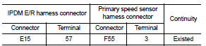
Is the check result normal? YES >> GO TO 7.
NO >> Repair or replace the malfunctioning parts.
7.CHECK CIRCUIT BETWEEN IPDM E/R AND PRIMARY SPEED SENSOR (PART 2)
Check continuity between IPDM E/R harness connector terminal and ground.
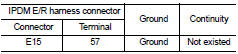
Is the check result normal? YES >> GO TO 8.
NO >> Repair or replace the malfunctioning parts.
8.DETECTION OF MALFUNCTION ITEMS
Check the following items: • Harness open circuit or short circuit between the ignition switch and IPDM E/R. Refer to PG-15, "Wiring Diagram - IGNITION POWER SUPPLY -".
• 10A fuse (No.55, IPDM E/R). Refer to PG-25, "Fuse, Connector and Terminal Arrangement".
• IPDM E/R Is the check result normal? YES >> Check intermittent incident. Refer to GI-42, "Intermittent Incident".
NO >> Repair or replace the malfunctioning parts.
 P0713 transmission fluid temperature sensor A
DTC Logic
DTC CONFIRMATION PROCEDURE
1.PREPARATION BEFORE WORK
If another "DTC CONFIRMATION PROCEDURE" occurs just before, turn ignition
switch OFF and wait for at
least 10 seconds, th ...
 P0720 output speed sensor
DTC Logic
DTC DETECTION LOGIC
DTC CONFIRMATION PROCEDURE
CAUTION:
Be careful of the driving speed.
1.PREPARATION BEFORE WORK
If another "DTC CONFIRMATION PROCEDURE" occurs just befor ...
Other materials:
The oil pressure warning lamp does not turn off
Description
The oil pressure warning lamp remains illuminated while the engine is running
(normal oil pressure).
Diagnosis Procedure
1.CHECK OIL PRESSURE WARNING LAMP
Perform auto active test. Refer to PCS-12, "Diagnosis Description" (with
I-KEY) or PCS-43, "Diagnosis
Descrip ...
Diagnosis system (ECM)
Diagnosis description
Diagnosis description : 1st Trip Detection
Logic and Two Trip Detection Logic
When a malfunction is detected for the first time, 1st trip DTC and 1st trip
Freeze Frame data are stored in the
ECM memory. The MIL will not illuminate at this stage. <1st trip>
If the s ...
Refrigeration system symptoms
Trouble Diagnosis For Unusual Pressure
Diagnose using a manifold gauge whenever system’s high and/or low side
pressure(s) is/are unusual. The
marker above the gauge scale in the following tables indicates the standard
(usual) pressure range. Refer to
above table (Ambient air temperature-to-op ...
