Nissan Juke Service and Repair Manual : P0711 transmission fluid temperature sensor A
DTC Logic
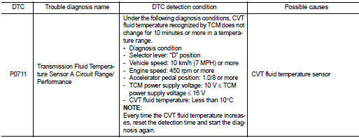
DTC DETECTION LOGIC
DTC CONFIRMATION PROCEDURE
1.PREPARATION BEFORE WORK
If another "DTC CONFIRMATION PROCEDURE" occurs just before, turn ignition switch OFF and wait for at least 10 seconds, then perform the next test.
>> GO TO 2.
2.PERFORM DTC CONFIRMATION PROCEDURE
1. Start the engine.
2. Drive the vehicle.
3. Maintain the following conditions for a total of 10 minutes or more.
Selector lever : “D” position Accelerator pedal position : 1.0/8 or more Vehicle speed : 20 km/h (12 MPH) or more
4. Stop the vehicle.
5. Check the first trip DTC.
Is “P0711” detected? YES >> Go to TM-419, "Diagnosis Procedure".
NO >> INSPECTION END
Diagnosis Procedure
1.CHECK CVT FLUID TEMPERATURE SENSOR
1. Turn ignition switch OFF.
2. Disconnect the CVT unit connector.
3. Check the CVT fluid temperature sensor. Refer to TM-405, "Component Inspection (CVT Fluid Temperature Sensor)".
Is the inspection result normal? YES >> Check intermittent incident. Refer to GI-42, "Intermittent Incident".
NO >> Repair or replace the malfunctioning parts.
Component Inspection (CVT Fluid Temperature Sensor)
1.CHECK CVT FLUID TEMPERATURE SENSOR
Check resistance between the CVT unit connector terminals.
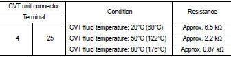
Is the inspection result normal? YES >> INSPECTION END
NO >> There is a malfunction of the CVT fluid temperature sensor. Replace the transaxle assembly.
Refer to TM-508, "Removal and Installation".
 P0706 transmission range sensor A
DTC Logic
DTC DETECTION LOGIC
DTC CONFIRMATION PROCEDURE
1.PREPARATION BEFORE WORK
If another "DTC CONFIRMATION PROCEDURE" occurs just before, turn ignition
switch OFF and wait for a ...
 P0712 transmission fluid temperature sensor A
DTC Logic
DTC DETECTION LOGIC
DTC CONFIRMATION PROCEDURE
1.PREPARATION BEFORE WORK
If another "DTC CONFIRMATION PROCEDURE" occurs just before, turn ignition
switch OFF and wait for a ...
Other materials:
Wiring diagram
BRAKE CONTROL SYSTEM
Wiring Diagram
For connector terminal arrangements, harness layout, and alphabets in a
(option abbreviation; if not
described in wiring diagram), refer to GI-12, "Connector Information/Explanation
of Option Abbreviation".
...
Filament
Inspection and Repair
INSPECTION
1. When measuring voltage, wrap tin foil around the top of the negative
probe. Then press the foil against the wire with your finger.
2. Attach probe circuit tester (in Volt range) to middle portion of
each filament.
3. If a filament is burned out, circuit ...
Precaution Necessary for Steering Wheel Rotation after Battery Disconnect
NOTE:
• Before removing and installing any control units, first turn the ignition
switch to the LOCK position, then disconnect
both battery cables.
• After finishing work, confirm that all control unit connectors are connected
properly, then re-connect both
battery cables.
• Always use CONS ...
