Nissan Juke Service and Repair Manual : P0705 transmission range switch A
DTC Logic
DTC DETECTION LOGIC
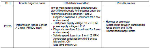
DTC CONFIRMATION PROCEDURE
CAUTION:
Be careful of the driving speed
.
1.PREPARATION BEFORE WORK
If another "DTC CONFIRMATION PROCEDURE" occurs just before, turn ignition switch OFF and wait for at least 10 seconds, then perform the next test.
>> GO TO 2.
2.CHECK DTC DETECTION
1. Start the engine.
2. Maintain the following conditions.
Accelerator pedal position : 0.0/8
Brake pedal : Depressed
Vehicle speed : 0 km/h (0 MPH)
3. Shift the selector lever through entire positions from “P” to “L”. (Hold
the selector lever at each position for
10 seconds or more.)
4. Check the first trip DTC.
Is “P0705” detected? YES >> Go to TM-394, "Diagnosis Procedure".
NO >> INSPECTION END
Diagnosis Procedure
1.CHECK TCM INPUT SIGNALS
 With CONSULT-III
1. Turn ignition switch ON.
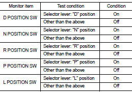
2. Select “Data Monitor” in “TRANSMISSION”.
3. Select “D POSITION SW”, “N POSITION SW”, “R POSITION SW”, “P POSITION SW” and “L POSITION SW”.
4. Shift the selector lever through entire positions from “P” to “L” and check ON/OFF of each monitor item.
 Without CONSULT-III.
1. Turn the ignition switch OFF.
2. Disconnect the TCM connector.
3. Turn ignition switch ON.
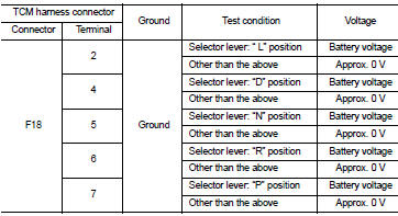
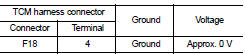
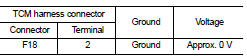
4. Shift the selector lever from “P” to “L” and check the voltage between the TCM harness connector terminal and the ground.
Is the check result normal? YES >> Check intermittent incident. Refer to GI-42, "Intermittent Incident".
NO-1 [“D POSITION SW” is “ON” when selector is not in “D” position. (Or connector terminal 4 is at power voltage.)]>>GO TO 2.
NO-2 [“N POSITION SW” is “ON” when selector is not in “N” position. (Or connector terminal 5 is at power voltage.)]>>GO TO 4.
NO-3 [“R POSITION SW” is “ON” when selector is not in “R” position. (Or connector terminal 6 is at power voltage.)]>>GO TO 6.
NO-4 [“P POSITION SW” is “ON” when selector is not in “P” position. (Or connector terminal 7 is at power voltage.)]>>GO TO 8.
NO-5 [“L POSITION SW” is “ON” when selector is not in “L” position. (Or connector terminal 2 is at power voltage.)]>>GO TO 10.
2.CHECK D POSITION SW CIRCUIT (PART 1)
1. Turn the ignition switch OFF.
2. Disconnect the TCM connector.
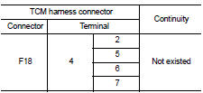
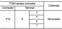
3. Check the continuity between the TCM harness connector terminals.
Is the check result normal? YES >> GO TO 3.
NO >> Repair or replace the malfunctioning parts.
3.CHECK D POSITION SW CIRCUIT (PART 2)
1. Disconnect the transmission position switch connector.
2. Turn ignition switch ON.
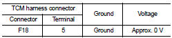
3. Check the voltage between the TCM harness connector and ground.
Is the check result normal? YES >> GO TO 12.
NO >> Repair or replace the malfunctioning parts.
4.CHECK N POSITION SW CIRCUIT (PART 1)
1. Turn the ignition switch OFF.
2. Disconnect the TCM connector.
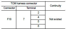
3. Check the continuity between the TCM harness connector terminals.
Is the check result normal? YES >> GO TO 5.
NO >> Repair or replace the malfunctioning parts.
5.CHECK N POSITION SW CIRCUIT (PART 2)
1. Disconnect the transmission position switch connector.
2. Turn ignition switch ON.
3. Check the voltage between the TCM harness connector and ground.
Is the check result normal? YES >> GO TO 12.
NO >> Repair or replace the malfunctioning parts.
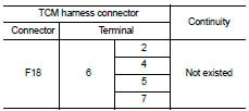
6.CHECK P POSITION SW CIRCUIT (PART 1)
1. Turn the ignition switch OFF.
2. Disconnect the TCM connector.
3. Check the continuity between the TCM harness connector terminals.
Is the check result normal? YES >> GO TO 7.
NO >> Repair or replace the malfunctioning parts.
7.CHECK P POSITION SW CIRCUIT (PART 2)
1. Disconnect the transmission position switch connector.
2. Turn ignition switch ON.
3. Check the voltage between the TCM harness connector and ground.
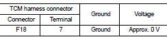
Is the check result normal? YES >> GO TO 12.
NO >> Repair or replace the malfunctioning parts.
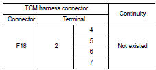
8.CHECK R POSITION SW CIRCUIT (PART1)
1. Turn the ignition switch OFF.
2. Disconnect the TCM connector.
3. Check the continuity between the TCM harness connector terminals
Is the check result normal? YES >> GO TO 9.
NO >> Repair or replace the malfunctioning parts.
9.CHECK R POSITION SW CIRCUIT (PART 2)
1. Disconnect the transmission position switch connector.
2. Turn ignition switch ON.
3. Check the voltage between the TCM harness connector and ground.
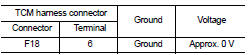
Is the check result normal? YES >> GO TO 12.
NO >> Repair or replace the malfunctioning parts.
10.CHECK 1: L POSITION SWITCH CIRCUIT (PART 1)
1. Turn the ignition switch OFF.
2. Disconnect the TCM connector.
3. Check the continuity between the TCM harness connector terminals.
Is the check result normal? YES >> GO TO 11.
NO >> Repair or replace the malfunctioning parts.
11.CHECK 2: L POSITION SWITCH CIRCUIT (PART 2)
1. Disconnect the transmission position switch connector.
2. Turn ignition switch ON.
3. Check the voltage between the TCM harness connector and ground.
Is the check result normal? YES >> GO TO 12.
NO >> Repair or replace the malfunctioning parts.
12.CHECK TRANSMISSION RANGE SWITCH
Check the transmission range switch. Refer to TM-398, "Component Inspection (Transmission Range Switch)".
Is the check result normal? YES >> Check intermittent incident. Refer to GI-42, "Intermittent Incident".
NO >> Repair or replace the malfunctioning parts.
Component Inspection (Transmission Range Switch)
1.CHECK TRANSMISSION RANGE SWITCH
Check the continuity between the transmission range switch connector terminals.
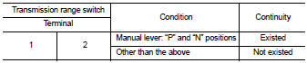
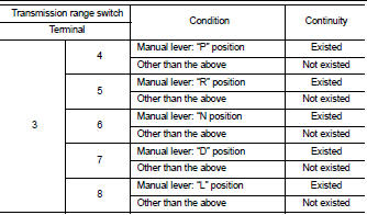
Is the inspection result normal? YES >> INSPECTION END
NO >> There is a malfunction of the transmission range switch. Replace the transaxle assembly. Refer to TM-508, "Removal and Installation".
 P062f eeprom
DTC Logic
DTC DETECTION LOGIC
DTC CONFIRMATION PROCEDURE
1.PREPARATION BEFORE WORK
If another "DTC CONFIRMATION PROCEDURE" occurs just before, turn ignition
switch OFF and wait for a ...
 P0706 transmission range sensor A
DTC Logic
DTC DETECTION LOGIC
DTC CONFIRMATION PROCEDURE
1.PREPARATION BEFORE WORK
If another "DTC CONFIRMATION PROCEDURE" occurs just before, turn ignition
switch OFF and wait for a ...
Other materials:
Removal and installation
PUSH-BUTTON IGNITION SWITCH
Removal and Installation
REMOVAL
1. Remove the NATS antenna amp. Refer to SEC-167, "Removal and
Installation".
2. Remove the push-button ignition switch.
1. Disengage the push-button ignition switch fixing pawls
using minus driver etc.
2. Press the pu ...
ANTI-HIJACK function does not operate
Diagnosis Procedure
1.CHECK “DOOR LOCK–UNLOCK SET” SETTING IN “WORK SUPPORT”
1. Select “DOOR LOCK” of “BCM” using CONSULT-III.
2. Select “DOOR LOCK-UNLOCK SET” in “WORK SUPPORT” mode.
3. Check “DOOR LOCK-UNLOCK SET” in “WORK SUPPORT”
Refer to DLK-501, "DOOR LOCK : CONSULT-III Function (BCM ...
Compression pressure
Inspection
1. Warm up engine thoroughly. Then, stop it.
2. Release fuel pressure. Refer to EC-551, "Work Procedure".
3. Remove ignition coil and spark plug from each cylinder. Refer to EM-53,
"Exploded View".
4. Connect engine tachometer (not required in use of CONSULT-II ...
