Nissan Juke Service and Repair Manual : P0506 ISC system
Description
The ECM controls the engine idle speed to a specified level through the fine adjustment of the air, which is let into the intake manifold, by operating the electric throttle control actuator. The operating of the throttle valve is varied to allow for optimum control of the engine idling speed. The crankshaft position sensor (POS) detects the actual engine speed and sends a signal to the ECM.
The ECM controls the electric throttle control actuator so that the engine speed coincides with the target value memorized in the ECM. The target engine speed is the lowest speed at which the engine can operate steadily.
The optimum value stored in the ECM is determined by taking into consideration various engine conditions, such as during warming up, deceleration, and engine load (air conditioner, power steering and cooling fan operation, etc.).
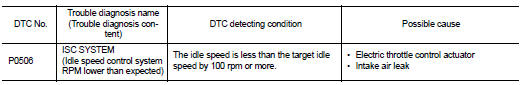
DTC Logic
DTC DETECTION LOGIC
NOTE
:
If DTC P0506 is displayed with other DTC, first perform the trouble diagnosis
for the other DTC.
DTC CONFIRMATION PROCEDURE
1.PRECONDITIONING
If DTC Confirmation Procedure has been previously conducted, always perform the following procedure before conducting the next test.
1. Turn ignition switch OFF and wait at least 10 seconds.
2. Turn ignition switch ON.
3. Turn ignition switch OFF and wait at least 10 seconds.
If the target idle speed is out of the specified value, performEC-136, "Work Procedure", before conducting DTC Confirmation Procedure.
TESTING CONDITION:
• Before performing the following procedure, confirm that battery voltage is
more than 11 V at idle.
• Always perform the test at a temperature above −10°C (14°F).
>> GO TO 2.
2.PERFORM DTC CONFIRMATION PROCEDURE
1. Start engine and warm it up to normal operating temperature.
2. Turn ignition switch OFF and wait at least 10 seconds.
3. Start engine and run it for at least 1 minute at idle speed.
4. Check 1st trip DTC.
Is 1st trip DTC detected? YES >> Proceed to EC-289, "
NO >> INSPECTION END
Diagnosis Procedure
1.CHECK INTAKE AIR LEAK
1. Start engine and let it idle.
2. Listen for an intake air leak after the mass air flow sensor.
Is intake air leak detected? YES >> Discover air leak location and repair.
NO >> Replace ECM. Refer to EC-447, "Removal and Installation".
 P0501, P2159 vehicle speed sensor
Description
ECM receives a rear wheel sensor signal from ABS actuator and electric unit
(control unit) via CAN communication
to switch combustion for the direct injection gasoline system. For the ...
 P0507 ISC system
Description
The ECM controls the engine idle speed to a specified level through the fine
adjustment of the air, which is let
into the intake manifold, by operating the electric throttle control ac ...
Other materials:
Condenser
Exploded View
1. Condenser
2. Condenser lower bracket RH
3. Condenser lower bracket LH
4. O-ring
5. Liquid tank braket
6. Liquid tank
7. Braket
8. O-ring
9. Refrigerant pressure sensor
: Do not reuse
: N·m (kg-m, in-lb)
: N·m (kg-m, ft-lb)
Condenser : Removal and Installation
C ...
Precaution Necessary for Steering Wheel Rotation after Battery Discon
NOTE:
• Before removing and installing any control units, first turn the ignition
switch to the LOCK position, then disconnect
both battery cables.
• After finishing work, confirm that all control unit connectors are connected
properly, then re-connect both
battery cables.
• Always use CONS ...
CVT control system
Wiring diagram
For connector terminal arrangements, harness layouts, and alphabets in a
(option abbreviation; if not
described in wiring diagram), refer to GI-12, "Connector Information/Explanation
of Option Abbreviation".
...
