Nissan Juke Service and Repair Manual : P047B exhaust gas pressure sensor 2
DTC Logic
DTC DETECTION LOGIC
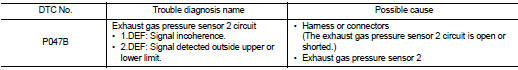
Diagnosis Proce
1.CHECK GROUND CONNECTIONS
1. Turn ignition switch OFF and wait at least 20 seconds.
2. Check ground connection E38. Refer to Ground inspection in GI-44, "Circuit Inspection".
Is the inspection result normal? YES >> GO TO 2.
NO >> Repair or replace ground connection.
2.CHECK EXHAUST GAS PRESSURE SENSOR 2 POWER SUPPLY CIRCUIT
1. Disconnect exhaust gas pressure sensor 2 harness connector.
2. Turn ignition switch ON.
3. Check the voltage between exhaust pressure sensor 2 harness connector and ground.
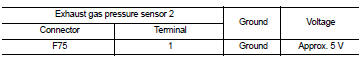
Is the inspection result normal? YES >> GO TO 3.
NO >> Repair open circuit or short to ground or short to power in harness or connectors.
3.CHECK EXHAUST GAS PRESSURE SENSOR 2 GROUND CIRCUIT FOR OPEN AND SHORT
1. Turn ignition switch OFF and wait at least 20 seconds.
2. Check the continuity between exhaust gas pressure sensor 2 harness connector and ECM harness connector.
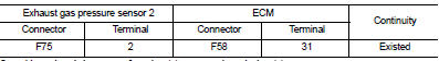
3. Also check harness for short to ground and short to power.
Is the inspection result normal? YES >> GO TO 4.
NO >> Repair open circuit or short to ground or short to power in harness or connectors.
4.CHECK EXHAUST GAS PRESSURE SENSOR 2 INPUT SIGNAL CIRCUIT FOR OPEN AND SHORT
1. Check the continuity between exhaust gas pressure sensor 2 harness connector and ECM harness connector.
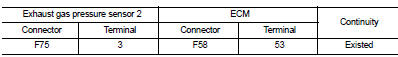
2. Also check harness for short to ground and short to power.
Is the inspection result normal? YES >> GO TO 5.
NO >> Repair open circuit or short to ground or short to power in harness or connectors.
5.CHECK INTERMITTENT INCIDENT
Refer to GI-42, "Intermittent Incident".
Is the inspection result normal? YES >> Replace exhaust gas pressure sensor 2.
NO >> Repair or replace.
 P047A exhaust gas pressure sensor 2
DTC Logic
DTC DETECTION LOGIC
NOTE:
If DTC P047A is displayed with DTC P0651, first perform trouble diagnosis for
DTC P0651. Refer to EC-975,
"DTC Logic".
Diagnosis Procedure
1.CHE ...
 P0487 EGR volume control valve
DTC Logic
DTC DETECTION LOGIC
Diagnosis Procedure
1.CHECK EGR VOLUME CONTROL VALVE CONTROL CIRCUIT
1. Turn ignition switch OFF.
2. Disconnect EGR volume control valve harness connector and ECM ...
Other materials:
Component parts
Component Parts Location
LHD models
1. ABS actuator and electric unit (control
unit)
Refer to BRC-97, "Component Parts
Location".
2. ECM
Refer to EC-25, "ENGINE CONTROL
SYSTEM :
Component Parts Location".
3. Front wheel sensor
Refer to BRC-97, "Component Parts
...
Removal and Installation
REMOVAL
1. Remove rear propeller shaft assembly. Refer to DLN-121, "Removal and
Installation".
2. Remove rear drive shaft. Refer to RAX-17, "Removal and Installation".
3. Disconnect sub-harness connector (1).
4. Remove rear final drive breather hose.
5. Support rear final ...
Operation inspection
Work Procedure
The purpose of the operational check is to check that the individual system
operates normally.
Check condition : Engine running at normal operating temperature.
1.CHECK BLOWER MOTOR
1. Operate fan control dial.
2. Check that fan speed changes. Check operation for all fan speeds ...
