Nissan Juke Service and Repair Manual : P0403 EGR volume control valve
DTC Logic
DTC DETECTION LOGIC
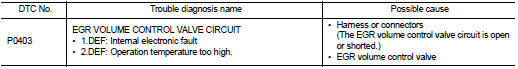
Diagnosis Procedure
1.CHECK EGR VOLUME CONTROL VALVE CONTROL CIRCUIT
1. Turn ignition switch OFF.
2. Disconnect EGR volume control valve harness connector and ECM harness connector.
3. Check the continuity between EGR volume control valve terminal harness connector and ECM harness connector
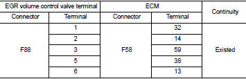
4. Also check harness for short to ground and short to power.
OK or NG OK >> GO TO 2.
NG >> Repair open circuit or short to ground or short to power in harness or connectors.
2.CHECK EGR VOLUME CONTROL VALVE
Refer to EC-941, "Component Inspection".
OK or NG OK >> GO TO 3.
NG >> Replace EGR volume control valve.
3.CHECK EGR VOLUME CONTROL VALVE CONTROL POSITION SENSOR
Refer to EC-941, "Component Inspection".
OK or NG OK >> GO TO 4.
NG >> Replace EGR volume control valve.
4.CHECK EGR PASSAGE
Check the following for clogging and cracks.
• EGR tube
• EGR hose
• EGR cooler
OK or NG OK >> GO TO 5.
NG >> Repair or replace EGR passage.
5.CHECK INTERMITTENT INCIDENT
Refer to GI-42, "Intermittent Incident".
>> INSPECTION END
Component Inspection
EGR VOLUME CONTROL VALVE
1. Disconnect EGR volume control valve harness connector.
2. Check resistance EGR volume control valve harness connector.
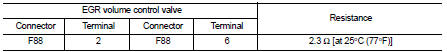
If NG, replace EGR volume control valve. Refer to EC-881, "Work Procedure".
EGR VOLUME CONTROL VALVE CONTROL POSITION SENSOR
1. Disconnect EGR volume control valve harness connector.
2. Check continuity EGR volume control valve harness connector.
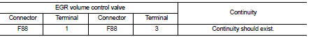
If NG, replace EGR volume control valve. Refer to EC-881, "Work Procedure".
 P0402 EGR volume control valve
DTC Logic
DTC DETECTION LOGIC
Diagnosis Procedure
1.CHECK GROUND CONNECTIONS
1. Turn ignition switch OFF.
2. Check ground connection E38. Refer to Ground inspection in GI-44, "Circuit
In ...
 P0409 EGR volume control valve control position sensor
DTC Logic
DTC DETECTION LOGIC
Diagnosis Procedure
1.CHECK GROUND CONNECTIONS
1. Turn ignition switch OFF.
2. Check ground connection E38. Refer to Ground inspection in GI-44, "Circuit
In ...
Other materials:
P1551, P1552 battery current sensor
DTC Logic
DTC DETECTION LOGIC
DTC CONFIRMATION PROCEDURE
1.PRECONDITIONING
If DTC Confirmation Procedure has been previously conducted, always perform
the following before conducting
the next test.
1. Turn ignition switch OFF and wait at least 10 seconds.
2. Turn ignition switch ON.
3. ...
Keyfob battery
Exploded View
1. Upper case
2. Key
3. Switch cover
4. Switch rubber
5. Board surface
6. Battery
7. plate
8. Lower case
9. Screw
Removal and Installation
REMOVAL
1. Remove screw (9) on the rear of keyfob.
2. Place the key with the lower case (8) facing up. Set a screw-driver wrap ...
Diagnosis and repair work flow
Work Flow
OVERALL SEQUENCE
Reference 1··· Refer to AV-33, "MODELS WITH USB CONNECTION FUNCTION : Symptom
Table" (with USB
connection function) or AV-35, "MODELS WITHOUT USB CONNECTION FUNCTION : Symptom
Table" (without
USB connection function).
DETAILED FLOW
1.CHECK ...
