Nissan Juke Service and Repair Manual : P0237, P0238 TC boost sensor
DTC Logic
DTC DETECTION LOGIC
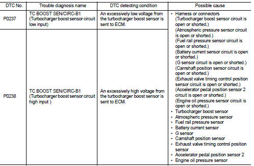
DTC CONFIRMATION PROCEDURE
1.PRECONDITIONING
If DTC Confirmation Procedure has been previously conducted, always perform the following procedure before conducting the next test.
1. Turn ignition switch OFF and wait at least 10 seconds.
2. Turn ignition switch ON.
3. Turn ignition switch OFF and wait at least 10 seconds.
>> GO TO 2.
2.PERFORM DTC CONFIRMATION PROCEDURE
1. Turn ignition switch ON and wait at least 5 seconds.
2. Check 1st trip DTC.
Is 1st trip DTC detected? YES >> Proceed to EC-260, "Diagnosis Procedure".
NO >> INSPECTION END
Diagnosis Procedure
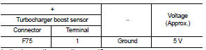
1.CHECK TURBOCHARGER BOOST SENSOR POWER SUPPLY
1. Disconnect turbocharger boost sensor harness connector.
2. Turn ignition switch ON.
3. Check the voltage between turbocharger boost sensor harness connector and ground.
Is the inspection result normal? YES >> GO TO 3.
NO >> GO TO 2.
2.CHECK SENSOR POWER SUPPLY CIRCUIT
1. Turn ignition switch OFF.
2. Disconnect ECM harness connector.
3. Check harness connector for short to power and short to ground, between the following terminals.
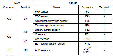
*1: LHD models or RHD with CVT models *2: RHD with M/T models
Is inspection result normal? YES >> Perform the trouble diagnosis for power supply circuit.
NO >> Repair or replace error-detected parts.
3.CHECK TURBOCHARGER BOOST SENSOR GROUND CIRCUIT
1. Turn ignition switch OFF.
2. Disconnect ECM harness connector.
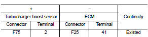
3. Check the continuity between turbocharger boost sensor harness connector and ECM harness connector.
4. Also check harness for short to power.
Is the inspection result normal? YES >> GO TO 4.
NO >> Repair or replace error-detected parts.
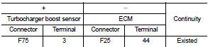
4.CHECK TURBOCHARGER BOOST SENSOR INPUT SIGNAL CIRCUIT
1. Check the continuity between turbocharger boost sensor harness connector and ECM harness connector.
2. Also check harness for short to ground and to power.
Is the inspection result normal? YES >> GO TO 5.
NO >> Repair or replace error-detected parts.
5.CHECK TURBOCHARGER BOOST SENSOR
Check the turbocharger boost sensor. Refer to EC-262, "Component Inspection".
Is the inspection result normal? YES >> Check intermittent incident. Refer to GI-42, "Intermittent Incident".
NO >> Replace turbocharger boost sensor. Refer to EM-36, "Exploded View".
Component Inspection
1.CHECK TURBOCHARGER BOOST SENSOR
1. Turn ignition switch OFF.
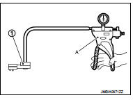
2. Remove turbocharger boost sensor with its harness connector.
3. Install pressure pump (A) to turbocharger boost sensor (1).
CAUTION:
When insert a pressure pump hose to the sensor, be careful
to the damage of the sensor housing.
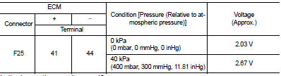
4. Turn ignition switch ON.
5. Check the voltage between ECM harness connector terminals as per the following conditions.
NOTE
:
• Always calibrate the pressure pump gauge when using it.
• Inspection should be done at room temperature [10 - 30°C (50 - 86°F)].
Is the inspection result normal? YES >> INSPECTION END NO >> Replace turbocharger boost sensor. Refer to EM-36, "Exploded View".
 P0234 TC system
DTC Logic
DTC DETECTION LOGIC
NOTE:
If DTC P0234 is displayed with DTC P0237 or P0238, first perform the trouble
diagnosis for DTC P0237 or
P0238. Refer to EC-260, "DTC Logic".
DTC ...
 P0300, P0301, P0302, P0303, P0304 misfire
DTC Logic
DTC DETECTION LOGIC
When a misfire occurs, engine speed will fluctuate. If the engine speed
fluctuates enough to cause the crankshaft
position (CKP) sensor (POS) signal to vary, ECM can ...
Other materials:
ECU diagnosis information
EPS control unit
Reference Value
VALUES ON THE DIAGNOSIS TOOL
CAUTION:
The output signal indicates the EPS control unit calculation data. The normal
values will be displayed
even in the event that the output circuit (harness) is open.
*1: Almost in accordance with the value of “MOTOR SIG”. ...
U0101 Can comm circuit
Description
CAN (Controller Area Network) is a serial communication line for real time
application. It is an on-vehicle multiplex
communication line with high data communication speed and excellent error
detection ability. Many electronic
control units are equipped onto a vehicle, and each c ...
ESP off indicator lamp
Component Function Check
1.CHECK ESP OFF INDICATOR LAMP FUNCTION (1)
Check that ESP OFF indicator lamp in combination meter turns ON for approx. 1
second after ignition switch is
turned ON.
CAUTION:
Never start engine.
Is the inspection result normal?
YES >> GO TO 2.
NO >> ...
