Nissan Juke Service and Repair Manual : P0117, P0118 ECT sensor
DTC Logic
DTC DETECTION LOGIC
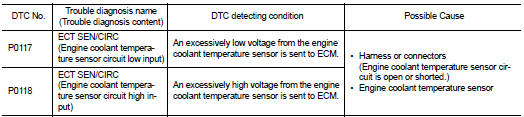
DTC CONFIRMATION PROCEDURE
1.PRECONDITIONING
If DTC Confirmation Procedure has been previously conducted, always perform the following procedure before conducting the next test.
1. Turn ignition switch OFF and wait at least 10 seconds.
2. Turn ignition switch ON.
3. Turn ignition switch OFF and wait at least 10 seconds.
>> GO TO 2.
2.PERFORM DTC CONFIRMATION PROCEDURE
1. Turn ignition switch ON and wait at least 5 seconds.
2. Check DTC.
Is DTC detected? YES >> Proceed to EC-200, "Diagnosis Procedure".
NO >> INSPECTION END
Diagnosis Procedure
1.CHECK ENGINE COOLANT TEMPERATURE SENSOR POWER SUPPLY
1. Turn ignition switch OFF.
2. Disconnect engine coolant temperature (ECT) sensor harness connector.
3. Turn ignition switch ON.
4. Check the voltage between ECT sensor harness connector and ground.
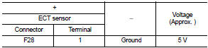
Is the inspection result normal? YES >> GO TO 3.
NO >> GO TO 2.
2.CHECK ENGINE COOLANT TEMPERATURE SENSOR POWER SUPPLY CIRCUIT
1. Turn ignition switch OFF.
2. Disconnect ECM harness connector.
3. Check the continuity between ECT sensor harness connector and ECM harness connector.
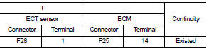
4. Also check harness for short to ground.
Is the inspection result normal? YES >> Perform the trouble diagnosis for power supply circuit.
NO >> Repair or replace error-detected parts.
3.CHECK ENGINE COOLANT TEMPERATURE SENSOR GROUND CIRCUIT
1. Turn ignition switch OFF.
2. Disconnect ECM harness connector.
3. Check the continuity between ECT sensor harness connector and ECM harness connector.
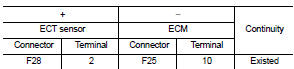
4. Also check harness for short to ground to power.
Is the inspection result normal? YES >> GO TO 4.
NO >> Repair or replace error-detected parts.
4.CHECK ENGINE COOLANT TEMPERATURE SENSOR
Check the engine coolant temperature sensor. Refer to EC-201, "Component Inspection".
Is the inspection result normal? YES >> Check intermittent incident. Refer to GI-42, "Intermittent Incident".
NO >> Replace engine coolant temperature sensor. Refer to EM-90, "Exploded View".
Component Inspection
1.CHECK ENGINE COOLANT TEMPERATURE SENSOR
1. Turn ignition switch OFF.
2. Disconnect engine coolant temperature sensor harness connector.
3. Remove engine coolant temperature sensor.
4. Check resistance between engine coolant temperature sensor terminals by heating with hot water as shown in the figure.
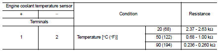
Is the inspection result normal? YES >> INSPECTION END NO >> Replace engine coolant temperature sensor. Refer to EM-90, "Exploded View".
 P0112, P0113 IAT sensor
DTC Logic
DTC DETECTION LOGIC
DTC CONFIRMATION PROCEDURE
1.PRECONDITIONING
If DTC Confirmation Procedure has been previously conducted, always perform
the following procedure
before conductin ...
 P0122, P0123 TP sensor
DTC Logic
DTC DETECTION LOGIC
NOTE:
If DTC P0122 or P0123 is displayed with DTC P0643, first perform the trouble
diagnosis for DTC P0643.
Refer to EC-307, "DTC Logic".
DTC CONFIRM ...
Other materials:
Precautions on seat belt usage
If you are wearing your seat belt properly adjusted, and you are sitting upright
and well back in your seat with both feet on the floor, your chances of being injured
or killed in an accident and/or the severity of injury may be greatly reduced. NISSAN
strongly encourages you and all of your p ...
Oil pan (lower)
Exploded View
1. O-ring
2. Oil pan (upper)
3. Oil level gauge guide
4. O-ring
5. Oil level gauge
6. Oil pump drive chain
7. Crankshaft sprocket
8. Oil pump sprocket
9. Oil pump chain tensioner
10. Oil pump
11. Drain plug
12. Drain plug washer
13. Oil pan (lower)
14. Oil fil ...
P1641 thermoplunger control unit
DTC Logic
DTC DETECTION LOGIC
Diagnosis Procedure
1.CHECK THERMOPLUNGER CONTROL UNIT POWER SUPPLY CIRCUIT
1. Turn ignition switch OFF.
2. Disconnect thermoplunger control unit harness connector.
3. Check the voltage between thermoplunger control unit harness connector and
ground.
Is the ...
