Nissan Juke Service and Repair Manual : P0107, P0108 atmospheric pressure sensor
DTC Logic
DTC DETECTION LOGIC
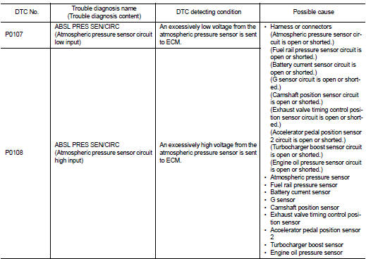
DTC CONFIRMATION PROCEDURE
1.PRECONDITIONING
If DTC Confirmation Procedure has been previously conducted, always perform the following procedure before conducting the next test.
1. Turn ignition switch OFF and wait at least 10 seconds.
2. Turn ignition switch ON.
3. Turn ignition switch OFF and wait at least 10 seconds.
>> GO TO 2.
2.PERFORM DTC CONFIRMATION PROCEDURE
1. Start engine and let it idle for 5 seconds.
2. Check 1st trip DTC.
Is 1st trip DTC detected? YES >> Proceed to EC-194, "Diagnosis Procedure".
NO >> INSPECTION END
Diagnosis Procedure
1.CHECK ATMOSPHERIC PRESSURE SENSOR POWER SUPPLY
1. Turn ignition switch OFF.
2. Disconnect atmospheric pressure sensor harness connector.
3. Turn ignition switch ON.
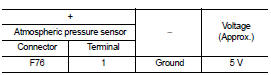
4. Check the voltage between atmospheric pressure sensor harness connector and ground.
Is the inspection result normal? YES >> GO TO 3.
NO >> GO TO 2.
2.CHECK SENSOR POWER SUPPLY CIRCUIT
1. Turn ignition switch OFF.
2. Disconnect ECM harness connector.
3. Check harness connector for short to power and short to ground, between the following terminals.
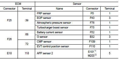
*1: LHD models or RHD with CVT models *2: RHD with M/T models
Is inspection result normal? YES >> Perform the trouble diagnosis for power supply circuit.
NO >> Repair or replace error-detected parts.
3.CHECK ATMOSPHERIC PRESSURE SENSOR GROUND CIRCUIT
1. Turn ignition switch OFF.
2. Disconnect ECM harness connector.
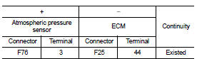
3. Check the continuity between atmospheric pressure sensor harness connector and ECM harness connector.
4. Also check harness for short to power.
Is the inspection result normal? YES >> GO TO 4.
NO >> Repair or replace error-detected parts.
4.CHECK ATMOSPHERIC PRESSURE SENSOR INPUT SIGNAL CIRCUIT
1. Check the continuity between atmospheric pressure sensor harness connector and ECM harness connector.
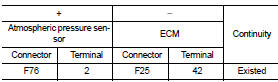
2. Also check harness for short to ground and to power.
Is the inspection result normal? YES >> GO TO 5.
NO >> Repair or replace error-detected parts.
5.CHECK ATMOSPHERIC PRESSURE SENSOR
Check the atmospheric pressure sensor. Refer to EC-196, "Component Inspection".
Is the inspection result normal? YES >> Check intermittent incident. Refer to GI-42, "Intermittent Incident".
NO >> Replace atmospheric pressure sensor. Refer to EC-447, "Removal and Installation".
Component Inspection
1.CHECK ATMOSPHERIC PRESSURE SENSOR
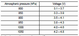
1. Turn ignition switch ON.
2. Check the voltage between ECM harness connector terminals as follows.
NOTE
:
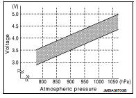
Because the sensor is absolute pressure sensor, output value may differ
depending on atmospheric pressure
and altitude.
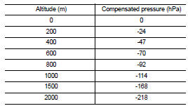
3. Measure the atmospheric pressure.
NOTE
:
As the atmospheric pressure described on the synoptic chart is the value at sea
level, compensate the
pressure with the following chart.
4. Check the atmospheric pressure sensor value corresponding to the atmospheric pressure.
Is the inspection result normal? YES >> INSPECTION END
NO >> Replace atmospheric pressure sensor. Refer to EC-447, "Removal and Installation".
 P0102, P0103 MAF sensor
DTC Logic
DTC DETECTION LOGIC
DTC CONFIRMATION PROCEDURE
1.PRECONDITIONING
If DTC Confirmation Procedure has been previously conducted, always perform
the following procedure
before conductin ...
 P0112, P0113 IAT sensor
DTC Logic
DTC DETECTION LOGIC
DTC CONFIRMATION PROCEDURE
1.PRECONDITIONING
If DTC Confirmation Procedure has been previously conducted, always perform
the following procedure
before conductin ...
Other materials:
Key warning lamp
Component Function Check
1.CHECK FUNCTION
1. Select “INTELLIGENT KEY” of “BCM” using CONSULT-III.
2. Select “INDICATOR” in “ACTIVE TEST” mode.
3. Check that the function operates normally according to the following
conditions.
Is the inspection result normal?
YES >> Key warning lamp ...
Service
• Never use electrical test equipment to check SRS circuits unless instructed
to in this Service Manual.
• Before servicing the SRS, turn ignition switch OFF, disconnect battery
negative terminal and wait 3 minutes
or more. For approximately 3 minutes after the cables are removed, it is still ...
Diagnosis system (PTC heater control unit)
CONSULT-III Function
CONSULT-III performs the following functions via CAN communication with PTC
heater control unit.
ECU IDENTIFICATION
Part number of PTC heater control unit can be checked.
SELF-DIAGNOSTIC RESULT
Diagnosis result that is judged by PTC heater control unit. can be checked ...
