Nissan Juke Service and Repair Manual : P0075 IVT control solenoid valve
DTC Logic
DTC DETECTION LOGIC
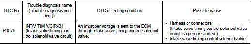
DTC CONFIRMATION PROCEDURE
1.PRECONDITIONING
If DTC Confirmation Procedure has been previously conducted, always perform the following procedure before conducting the next test.
1. Turn ignition switch OFF and wait at least 10 seconds.
2. Turn ignition switch ON.
3. Turn ignition switch OFF and wait at least 10 seconds
>> GO TO2.
2.PERFORM DTC CONFIRMATION PROCEDURE
1. Start engine and let it idle for 5 seconds.
2. Check 1st trip DTC.
Is 1st trip DTC detected? YES >> Proceed to EC-176,
Diagnosis Procedure
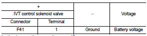
1.CHECK INTAKE VALVE TIMING CONTROL SOLENOID VALVE POWER SUPPLY
1. Turn ignition switch OFF.
2. Disconnect intake valve timing (IVT) control solenoid valve harness connector.
3. Turn ignition switch ON.
4. Check the voltage between intake valve timing control solenoid valve harness connector and ground.
Is the inspection result normal? YES >> GO TO 3.
NO >> GO TO 2.
2.CHECK INTAKE VALVE TIMING CONTROL SOLENOID VALVE POWER SUPPLY CIRCUIT
1. Turn ignition switch OFF.
2. Disconnect IPDM E/R harness connector.
3. Check the continuity between IVT control solenoid valve harness connector and IPDM E/R harness connector.
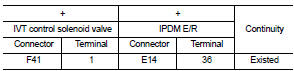
4. Also check harness for short to ground.
Is the inspection result normal? YES >> Perform the trouble diagnosis for power supply circuit.
NO >> Repair or replace error-detected parts.
3.CHECK INTAKE VALVE TIMING CONTROL SOLENOID VALVE GROUND CIRCUIT
1. Turn ignition switch OFF.
2. Disconnect ECM harness connector.
3. Check the continuity between IVT control solenoid valve harness connector and ECM harness connector.
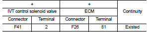
4. Also check harness for short to ground and to power.
Is the inspection result normal? YES >> GO TO 4.
NO >> Repair or replace error-detected parts.
4.CHECK INTAKE VALVE TIMING CONTROL SOLENOID VALVE
Check the intake valve timing control solenoid valve. Refer to EC-177, "Component Inspection".
Is the inspection result normal? YES >> Check intermittent incident. Refer to GI-42, "Intermittent Incident".
NO >> Replace intake valve timing control solenoid valve.
Component Inspection
1.CHECK INTAKE VALVE TIMING CONTROL SOLENOID VALVE-I
1. Turn ignition switch OFF.
2. Disconnect intake valve timing control solenoid valve harness connector.
3. Check resistance between intake valve timing control solenoid valve terminals as per the following.
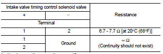
Is the inspection result normal? YES >> GO TO 2.
NO >> Replace intake valve timing control solenoid valve. Refer to EM-67, "Exploded View".
2.CHECK INTAKE VALVE TIMING CONTROL SOLENOID VALVE-II
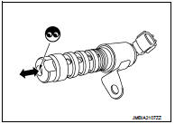
1. Remove intake valve timing control solenoid valve. Refer to EM-67, "Exploded View".
2. Provide 12 V DC between intake valve timing control solenoid valve terminals 1 and 2, and then interrupt it. Make sure that the plunger moves as shown in the figure.
CAUTION:
Do not apply 12 V DC continuously for 5 seconds or more.
Doing so may result in damage to the coil in intake valve timing control solenoid valve.
NOTE:
Always replace O-ring when intake valve timing control solenoid valve is removed.
Is the inspection result normal? YES >> INSPECTION END NO >> Replace intake valve timing control solenoid valve. Refer to EM-67, "Exploded View".
 P0045, P0047, P0048 TC boost control
solenoid valve
P0045, P0047, P0048 TC boost control
solenoid valve
DTC Logic
DTC DETECTION LOGIC
DTC CONFIRMATION PROCEDURE
1.PRECONDITIONING
If DTC Confirmation Procedure has been previously conducted, always perform
the following procedure
before conductin ...
 P0078 EVT control solenoid valve
DTC Logic
DTC DETECTION LOGIC
DTC CONFIRMATION PROCEDURE
1.PRECONDITIONING
If DTC Confirmation Procedure has been previously conducted, always perform
the following procedure
before conductin ...
Other materials:
Precautions for Drive Shaft
• Observe the following precautions when disassembling and assembling drive
shaft.
- Never disassemble joint sub-assembly because it is non-overhaul parts.
- Perform work in a location which is as dust-free as possible.
- Clean the parts, before disassembling and assembling.
- Prevent the entr ...
U1000 can comm circuit
Description
CAN (Controller Area Network) is a serial communication line for real time
application. It is an on-vehicle multiplex
communication line with high data communication speed and excellent error
detection ability. Many electronic
control units are equipped onto a vehicle, and each co ...
Service
• Never use electrical test equipment to check SRS circuits unless instructed
to in this Service Manual.
• Before servicing the SRS, turn ignition switch OFF, disconnect battery
negative terminal and wait 3 minutes
or more. For approximately 3 minutes after the cables are removed, it is still ...
