Nissan Juke Service and Repair Manual : Operation
Switch Name and Function
OPERATION AND DISPLAY
A/C Display (Display in Multi Display Unit)
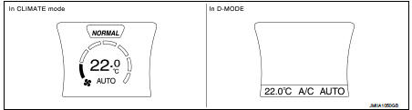
• Air conditioning system operation status is indicated on display in multi display unit. Indication of air conditioning system varies according to display mode of multi display unit. For changing procedure of display mode, refer to AV-99, "NISSAN DYNAMIC CONTROL SYSTEM : System Description".
- In CLIMATE mode: Operation status of air conditioning system (setting temperature, air flow, and “AUTO”*1) is indicated on display when air conditioning system is turned ON.
- In D-MODE: Operation status of air conditioning system (setting temperature, A/C switch, and “AUTO”*2) is indicated on lower portion of display when air conditioning system is turned ON.
NOTE
:
*1: AUTO is indicated when both air flow and air outlet are in automatic
control.
*2: Air Flow is indicated when air flow or air outlet is in manual control.
A/C Controller (Multi Display Unit) Operation procedure of air conditioning system varies depending on display mode of multi display unit. For changing procedure of display mode, refer to AV-99, "NISSAN DYNAMIC CONTROL SYSTEM : System Description".
• In CLIMATE mode: All operations of air conditioning system are possible.
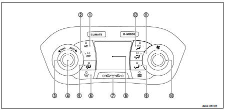
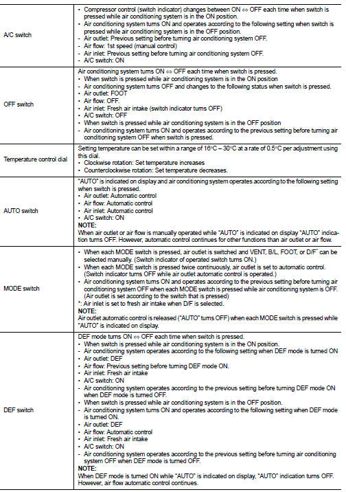
1. A/C switch
2. OFF switch
3. Temperature control dial
4. AUTO switch
5. MODE switch (D/F)
6. DEF switch
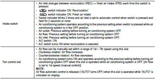
7. Intake switch
8. Display
9. MODE switch (FOOT)
10. Fan control dial
11. MODE switch (B/L)
12. MODE switch (VENT)
• In D-MODE: The following switches and dial cannot be operated.
- A/C switch
- OFF switch
- MODE switch
- Fan control dial
 System
Automatic air conditioning system : System Diagram
Automatic air conditioning system : System Description
DESCRIPTION
• Automatic air conditioning system is controlled by each function of A/C
a ...
 Diagnosis system (A/C auto AMP.)
Description
Air conditioning system performs self-diagnosis, operation check, function
diagnosis, and various settings
using diagnosis function of each control unit.
CONSULT-III Function
CONSU ...
Other materials:
P1212 TCS communication line
Description
This CAN communication line is used to control the smooth engine operation
during the TCS operation. Pulse
signals are exchanged between ECM and “ABS actuator and electric unit (control
unit)”.
Be sure to erase the malfunction information such as DTC not only for “ABS
actuator ...
P17B8 high clutch solenoid
DTC Logic
DTC DETECTION LOGIC
DTC CONFIRMATION PROCEDURE
1.PREPARATION BEFORE WORK
If another "DTC CONFIRMATION PROCEDURE" occurs just before, turn ignition
switch OFF and wait for at
least 10 seconds, then perform the next test.
>> GO TO 2.
2.CHECK DTC DETECTION
1. S ...
Components
• THE LARGE ILLUSTRATIONS are exploded views (see the following) and
contain tightening torques, lubrication
points, section number of the PARTS CATALOG (e.g. SEC. 440) and other
information necessary to
perform repairs.
The illustrations should be used in reference to service matters only. ...
